FINALIZED DESIGN & CONSTRUCTION
DEVICE
|
Improving on my mockup design, I scrapped the idea to have 5 removable faces and instead opted for just one.
I additionally changed my plans for having a base underneath the box for holding the light bulb/socket, deciding that a wooden bottom with a hole in it would be a more logical option. Aside from this, my design remained largely the same. 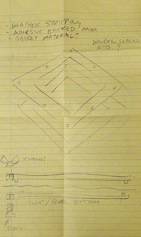
|
Left: Fig. 09 - Robby's suggestions for final design. This was made the day I constructed the box, when we were discussing how I should close it up.
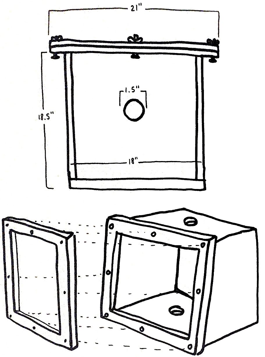
Above: Fig. 10 - Rough sketch of final design |
CONTROLS
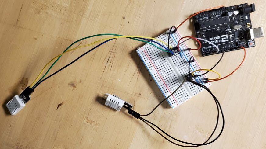
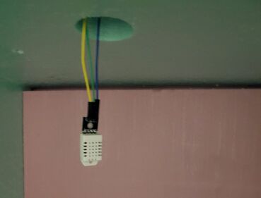
Above: Fig. 11 - The finished wiring for the electronics, and the DHT22 sensor inside of my device.
Below: Fig. 12 - A wiring diagram showing my goal for the electronics before assembly. 
|
For the electronic controls of the project, I used an Elegoo Uno board with two DHT22 Temperature/Humidity sensors. I edited an existing code to register two temperatures and display them simultaneously, taking readings every 5 minutes.
|
MATERIALS
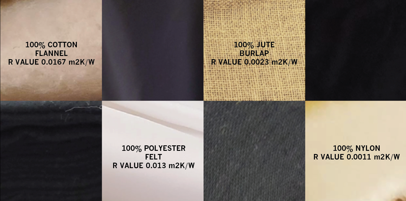
The four materials I've tested for this project are cotton, jute, polyester, and nylon. These came in the form of flannel, burlap, felt, and... nylon. I bought a yard of each material in black as well as white, and cut them into three 1.5' rectangular layers to put over the opening of the box.
|
Above: Fig. 13 - All of the materials I'm using for the experiment, and their R values.
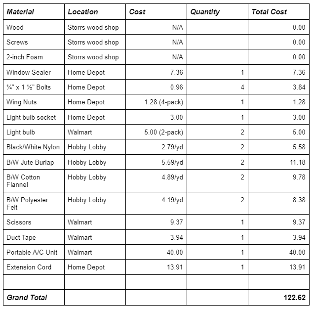
Right: Fig. 14 - the total cost for the materials I used. Below: Fig. 15 - One of many trips I made to the store during construction. Usually my trips were 50% materials I needed, 50% impulse-bought junk food. I'm excluding the junk food from the total cost to preserve my dignity. 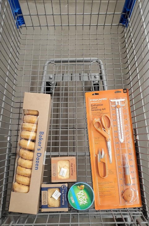
|
|
*SOME ASSEMBLY REQUIRED
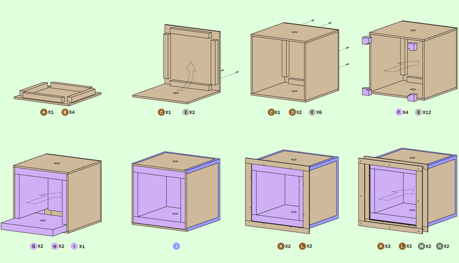
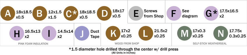
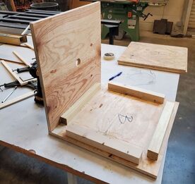
Fig. 17 - Step 2 in action at Storrs. The "B" visible in the picture has nothing to do with the labels I gave each piece for this tutorial.
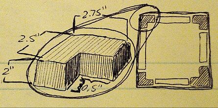
Fig. 18 - diagram of the pieces (F) used in step 4.
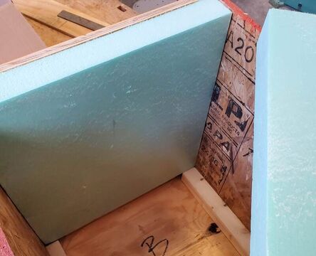
Fig 19 - Step 5 Behind-the-Scenes, inserting the foam (H) inside of the box while testing the size of the cuts
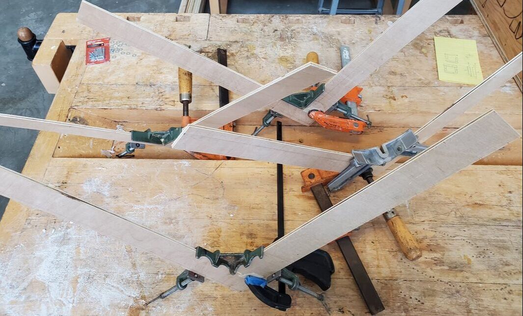
Fig 20 - Step 7 at Storrs.
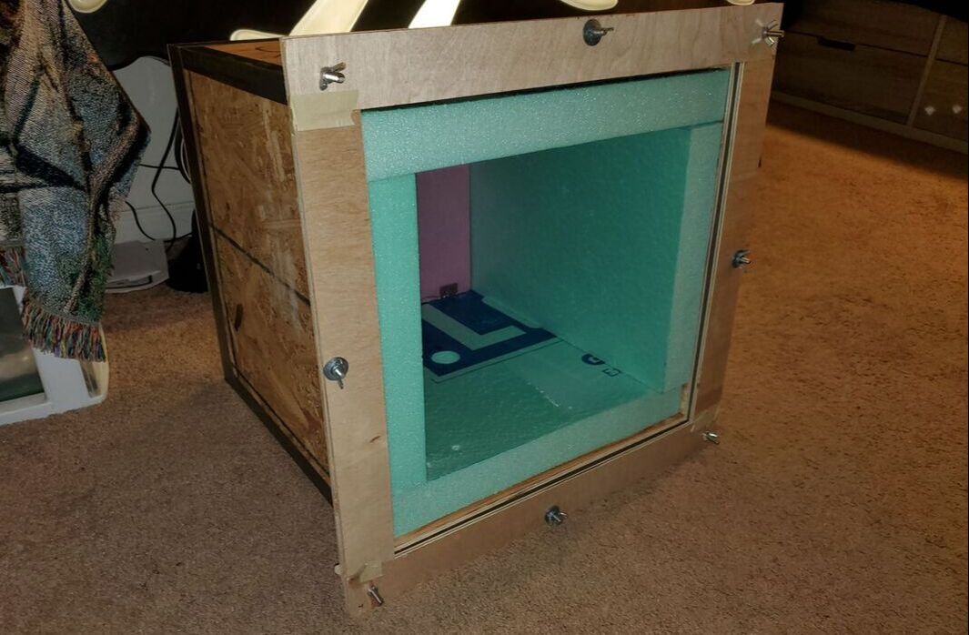
Fig 21 - Step 8 completed at my apartment.
|
Above: Fig. 16 - Assembly diagram and material key, respectively.
STEP 1 Glue all four (B) pieces to the back face of the box (A). STEP 2 Attach piece (C) to (A) by gluing the two and joining them at the edges of (B). Put screws (E) in to hold it in place. STEP 3 Attach the other (C) and two (D) pieces the same way. STEP 4 Insert the four corner pieces (F) to close up the gaps left behind from the wall assembly. STEP 5 Insert the back foam piece (I) and the four wall foam pieces (GH) into the box. STEP 6 Use duct tape (J) to cover the corners of the box. The edges should be closed tight, however the duct tape will help retain heat better and catch any potential leaks. STEP 7 Screw in the first face plate. The edges of pieces (K) and (L) are joined by gluing the two at the edges, then letting them dry in a 90 degree clamp. Once the 4 pieces are connected and dried for at least 2 hours, the plate is ready to go. Drill 8 holes into the plate-- four in each corner, and four in the center of each side. Use 8 screws (E) to attach it to the box, evenly spaced between each other and the edges of the wooden walls of the box. STEP 8 Peel and stick the rubber window sealer (MN) on the first face plate (the one screwed into the box). Drill 8 holes in the second plate to match the holes in the first one, and then attach the two with a 1/4" screw and wingnut in each hole. |
Slideshow of the drawings from Fig. 16.