Kit Contents
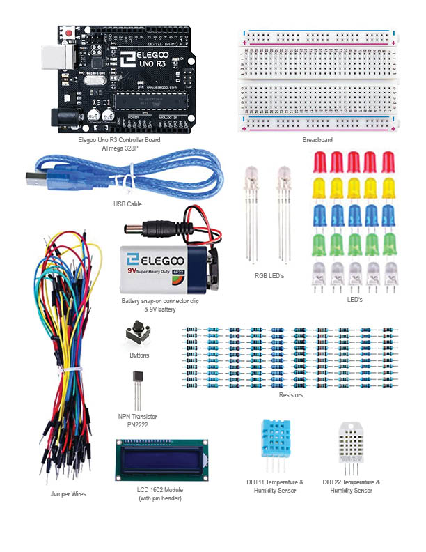
Electronics Workshop
You will need to download and install the Arduino software. (works on both mac and windows)
https://www.arduino.cc/en/main/software
Most of the workshop comes from the Elegoo Super Starter Kit for UNO Tutorial (download from Canvas)
You will also need to download the Elegoo sample codes from Canvas. Go to Files > 2-WORKSHOPS > Elegoo code folders
1. Run through Lesson 1 on your own (Add Libraries and Open Serial Monitor)
2. Lesson 2 - Blink
In this lesson, you will learn how to program your UNO R3 controller board to blink the Arduino’s built-in LED, and how to download programs by basic steps.
Component Required:
(1) x Elegoo Uno R3
Principle
The UNO R3 board has rows of connectors along both sides that are used to connect to several electronic devices and plug-in 'shields' that extends its capability. It also has a single LED that you can control from your sketches. This LED is built onto the UNO R3 board and is often referred to as the 'L' LED as this is how it is labeled on the board.
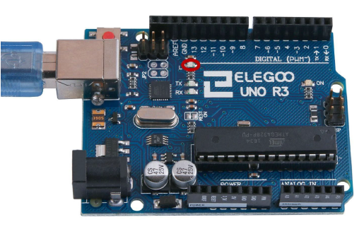
You may find that your UNO R3 board's 'L' LED already blinks when you connect it to a USB plug. This is because the boards are generally shipped with the 'Blink' sketch pre-installed.
|
|
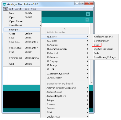
The Arduino IDE includes a large collection of example sketches that you can load up and use. This includes an example sketch for making the 'L' LED blink. Load the 'Blink' sketch that you will find in the IDE's menu system under File > Examples > 01.Basics
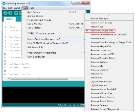
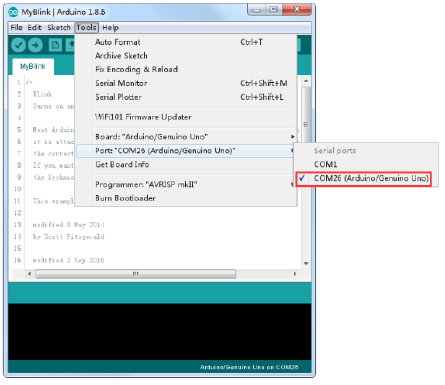
When the sketch window opens, enlarge it so that you can see the entire sketch in the window. Attach your Arduino board to your computer with the USB cable and check that the 'Board Type' and 'Serial Port' are set correctly.
When the sketch window opens, enlarge it so that you can see the entire sketch in the window. Attach your Arduino board to your computer with the USB cable and check that the 'Board Type' and 'Serial Port' are set correctly.
|
|
Note: The Board Type and Serial Port here are not necessarily the same as shown in picture. If you are using 2560, then you will have to choose Mega 2560 as the Board Type, other choices can be made in the same manner. And the Serial Port displayed for everyone is different, despite COM 26 chosen here, it could be COM3 or COM4 on your computer. A right COM port is supposed to be COMX (arduino XYZ), which is by the certification criteria. The Arduino IDE will show you the current settings for board at the bottom of the window.
Click on the 'Upload' button. The second button from the left on the toolbar. If you watch the status area of the IDE, you will see a progress bar and a series of messages. At first, it will say 'Compiling Sketch...'. This converts the sketch into a format suitable for uploading to the board. Next, the status will change to 'Uploading'. At this point, the LEDs on the Arduino should start to flicker as the sketch is transferred.
Finally, try changing the speed of the blink and re-upload the sketch.
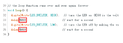
Inside the loop function, the commands first of all turn the LED pin on (HIGH), then 'delay' for 1000 milliseconds (1 second), then turn the LED pin off and pause for another second. You are now going to make your LED blink faster. As you might have guessed, the key to this lies in changing the parameter in () for the 'delay' command.
This delay period is in milliseconds, so if you want the LED to blink twice as fast, change the value from 1000 to 500. This would then pause for half a second each delay rather than a whole second. Upload the sketch again and you should see the LED start to blink more quickly.
Click on the 'Upload' button. The second button from the left on the toolbar. If you watch the status area of the IDE, you will see a progress bar and a series of messages. At first, it will say 'Compiling Sketch...'. This converts the sketch into a format suitable for uploading to the board. Next, the status will change to 'Uploading'. At this point, the LEDs on the Arduino should start to flicker as the sketch is transferred.
Finally, try changing the speed of the blink and re-upload the sketch.
Inside the loop function, the commands first of all turn the LED pin on (HIGH), then 'delay' for 1000 milliseconds (1 second), then turn the LED pin off and pause for another second. You are now going to make your LED blink faster. As you might have guessed, the key to this lies in changing the parameter in () for the 'delay' command.
This delay period is in milliseconds, so if you want the LED to blink twice as fast, change the value from 1000 to 500. This would then pause for half a second each delay rather than a whole second. Upload the sketch again and you should see the LED start to blink more quickly.
Lesson 4 - RGB LED
RGB LEDs are a fun and easy way to add some color to your projects. Since they are like 3 regular LEDs in one, how to use and connect them is not much different. They come mostly in 2 versions: Common Anode or Common Cathode.
Common Anode uses 5V on the common pin, while Common Cathode connects to ground. As with any LED, we need to connect some resistors inline (3 total) so we can limit the current being drawn.
In our sketch, we will start with the LED in the Red color state, then fade to Green, then fade to Blue and finally back to the Red color. By doing this we will cycle through most of the color that can be achieved.
Component Required:
(1) x Elegoo Uno R3
(1) x 830 Tie Points Breadboard
(4) x M-M wires (Male to Male jumper wires)
(1) x RGB LED
(3) x 220 ohm resistors
Component Introduction
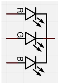
RGB: At first glance, RGB (Red, Green and Blue) LEDs look just like regular LEDs. However, inside the usual LED package, there are actually three LEDs, one red, one green and yes, one blue. By controlling the brightness of each of the individual LEDs you can mix pretty much any color you want.
We mix colors the same way you would mix paint on a palette - by adjusting the brightness of each of the three LEDs. The hard way to do this would be to use different value resistors (or variable resistors) as we did with in Lesson 2, but that's a lot of work! Fortunately for us, UNO R3 board has an analogWrite function that you can use with pins marked with a ~ to output a variable amount of power to the appropriate LEDs.
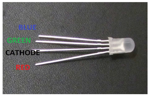
The RGB LED has four leads. There is one lead going to the positive connection of each of the single LEDs within the package and a single lead that is connected to all three negative sides of the LEDs.
RGB LEDs are a fun and easy way to add some color to your projects. Since they are like 3 regular LEDs in one, how to use and connect them is not much different. They come mostly in 2 versions: Common Anode or Common Cathode.
Common Anode uses 5V on the common pin, while Common Cathode connects to ground. As with any LED, we need to connect some resistors inline (3 total) so we can limit the current being drawn.
In our sketch, we will start with the LED in the Red color state, then fade to Green, then fade to Blue and finally back to the Red color. By doing this we will cycle through most of the color that can be achieved.
Component Required:
(1) x Elegoo Uno R3
(1) x 830 Tie Points Breadboard
(4) x M-M wires (Male to Male jumper wires)
(1) x RGB LED
(3) x 220 ohm resistors
Component Introduction
RGB: At first glance, RGB (Red, Green and Blue) LEDs look just like regular LEDs. However, inside the usual LED package, there are actually three LEDs, one red, one green and yes, one blue. By controlling the brightness of each of the individual LEDs you can mix pretty much any color you want.
We mix colors the same way you would mix paint on a palette - by adjusting the brightness of each of the three LEDs. The hard way to do this would be to use different value resistors (or variable resistors) as we did with in Lesson 2, but that's a lot of work! Fortunately for us, UNO R3 board has an analogWrite function that you can use with pins marked with a ~ to output a variable amount of power to the appropriate LEDs.
The RGB LED has four leads. There is one lead going to the positive connection of each of the single LEDs within the package and a single lead that is connected to all three negative sides of the LEDs.
|
|
Here on the photographs you can see 4 electrode LED. Every separate pin for Green or Blue or Red color is called Anode. You will always connect “+” to it. Cathode goes to “-“(ground). If you connect it other way round the LED will not light.
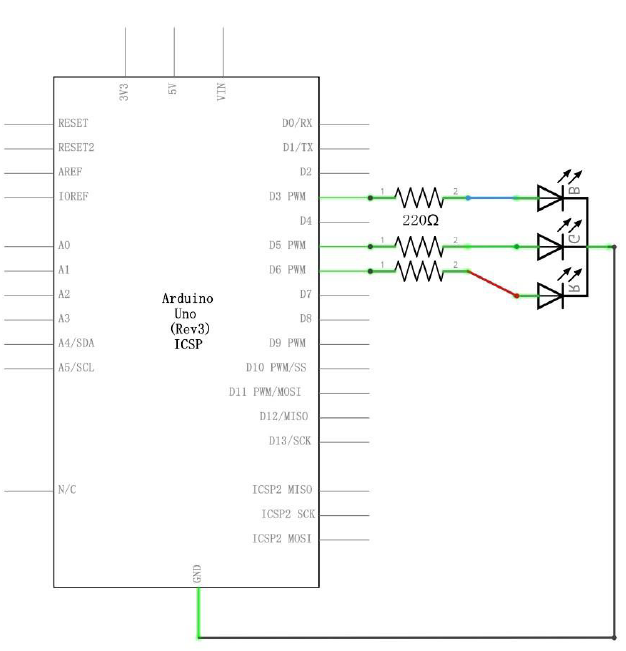
The common negative connection of the LED package is the second pin from the flat side. It is also the longest of the four leads and will be connected to the ground. Each LED inside the package requires its own 220Ω resistor to prevent too much current flowing through it. The three positive leads of the LEDs (one red, one green and one blue) are connected to UNO output pins using these resistors.
The common negative connection of the LED package is the second pin from the flat side. It is also the longest of the four leads and will be connected to the ground. Each LED inside the package requires its own 220Ω resistor to prevent too much current flowing through it. The three positive leads of the LEDs (one red, one green and one blue) are connected to UNO output pins using these resistors.
|
Schematic Diagram
|
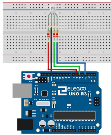
Wiring Diagram
|
Note: you will need to install the code libraries from Canvas before proceeding
Code
After wiring, please open the program in the code folder- Lesson 4 RGB LED, and click UPLOAD to upload the program. See Lesson 2 for details about program uploading if there are any errors.
Our code will use FOUR loops to cycle through the colors. The first FOR loop will go from RED to GREEN.
The second FOR loop will go from GREEN to BLUE. The last FOR loop will go from BLUE to RED.
For Homework:
Go through the Elegoo lessons 5 and 11.
If you are planning to measure temperature and humidity, you should also go through this tutorial:
https://create.arduino.cc/projecthub/mafzal/temperature-monitoring-with-dht22-arduino-15b013
Finally, make sure you post a clear diagram of your electronics control strategy so that we can start working through it during our next class. During that workshop, we will continue developing the electronics so that you can use more than one device at a time using the same code.