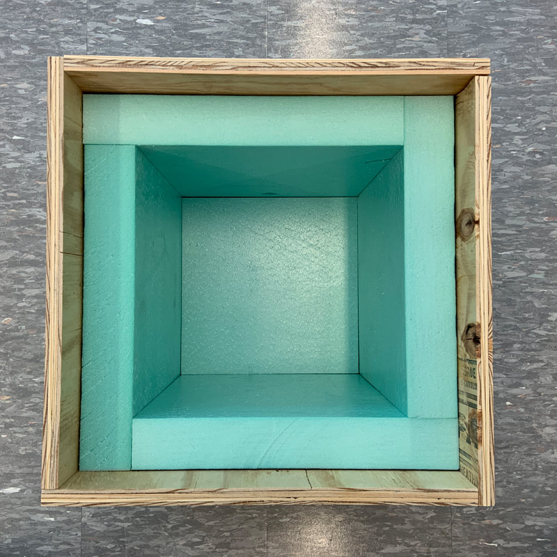
Plywood Shell
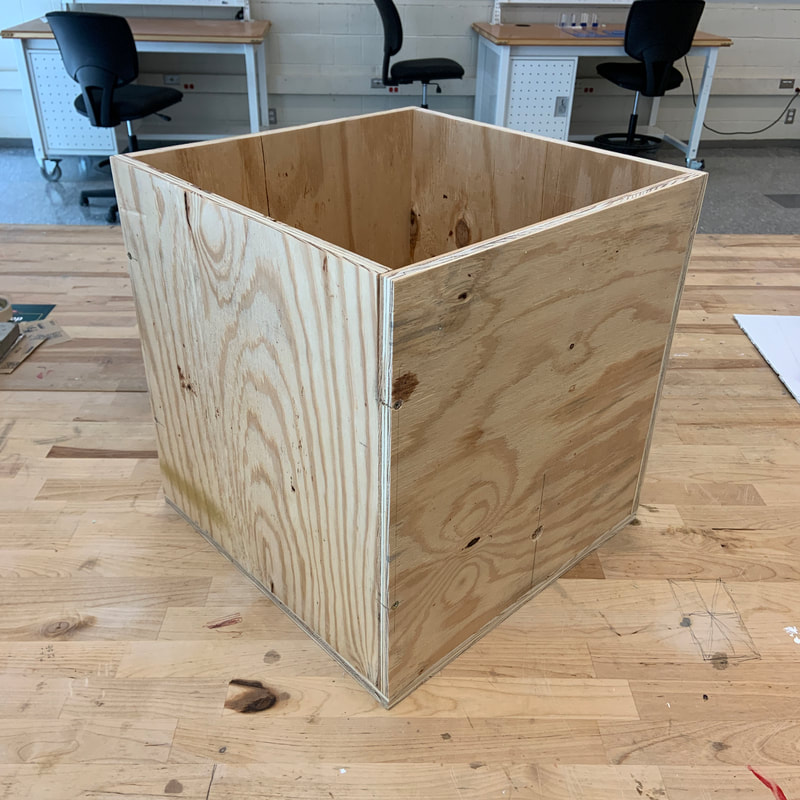
The first step of constructing the test enclosure involved cutting and assembling the pieces for the plywood shell. The sides of the box were to be arranged in a pinwheel configuration so that all four pieces would be equal-sized and interchangeable. The top and bottom would both be square.
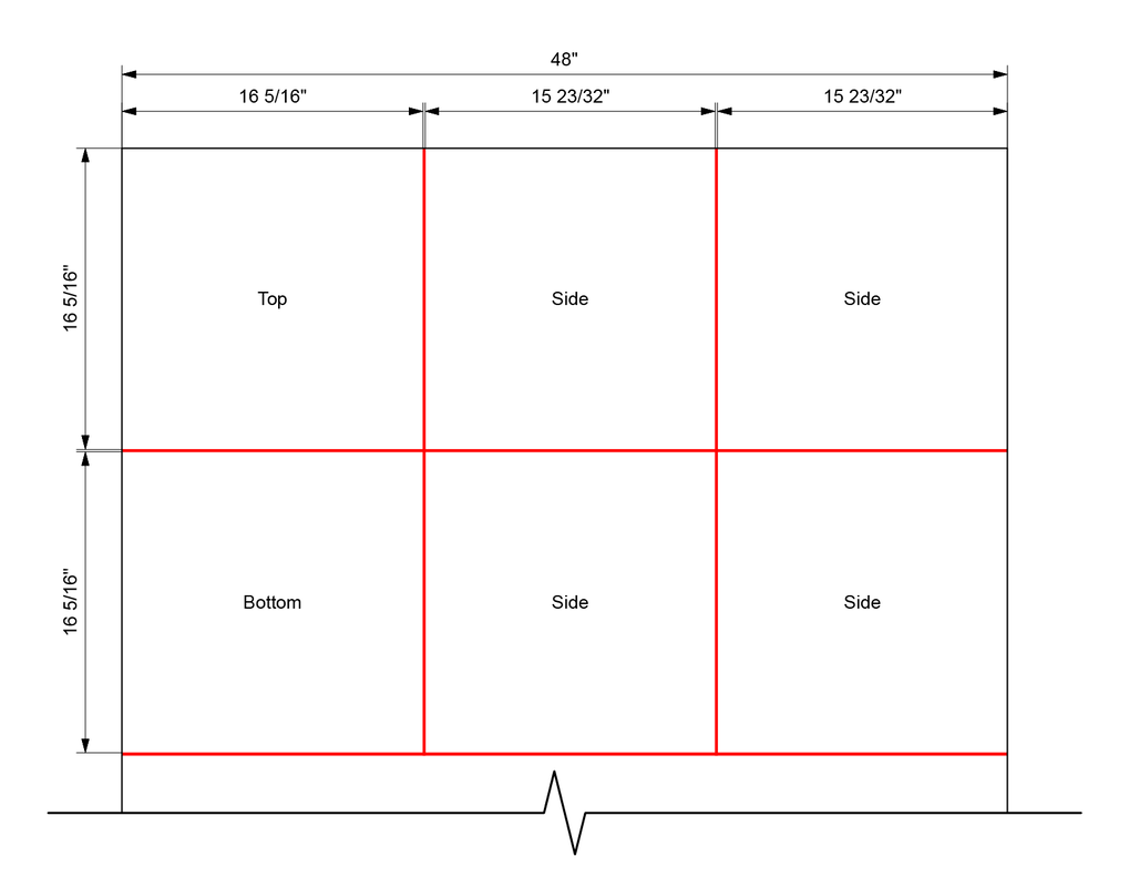
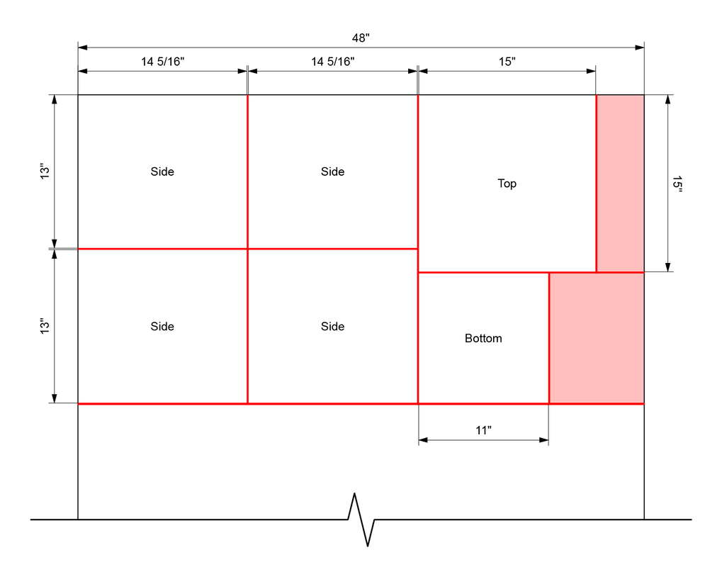
In order to minimize waste, the pieces were sized to take advantage of the entire width of a standard 4 foot by 8 foot sheet of plywood. The plywood itself was surplus material held by the school's fabrication lab, and was obtained at no cost. Given the geometric constraints of the design and a material thickness of approximately 19/32 inches, the pieces for the shell were cut according to the diagram below.
In order to minimize waste, the pieces were sized to take advantage of the entire width of a standard 4 foot by 8 foot sheet of plywood. The plywood itself was surplus material held by the school's fabrication lab, and was obtained at no cost. Given the geometric constraints of the design and a material thickness of approximately 19/32 inches, the pieces for the shell were cut according to the diagram below.
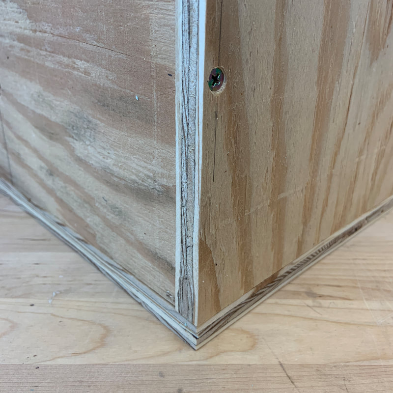
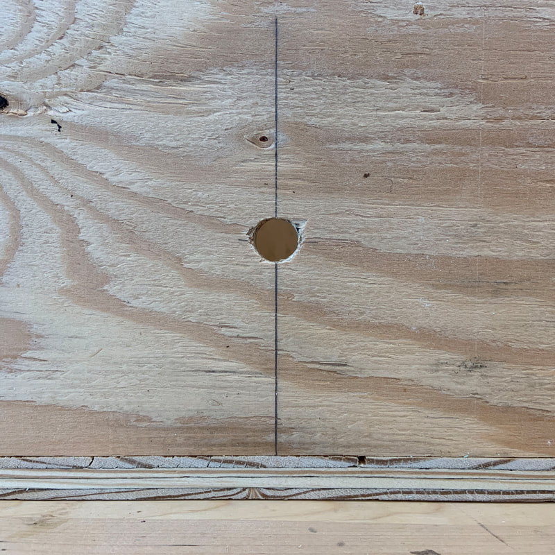
The plywood pieces were assembled using simple butt joints and held together with two countersunk screws on each edge. Holes for the screws were pre-drilled to avoid splitting the plywood during assembly. A 5/8 inch hole (below right) was also drilled through one of the sides of the shell for the tube that would carry water vapor from the humidifier into the test enclosure.
|
|
|
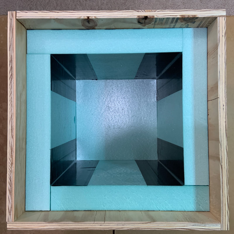
Rigid Foam Insulation
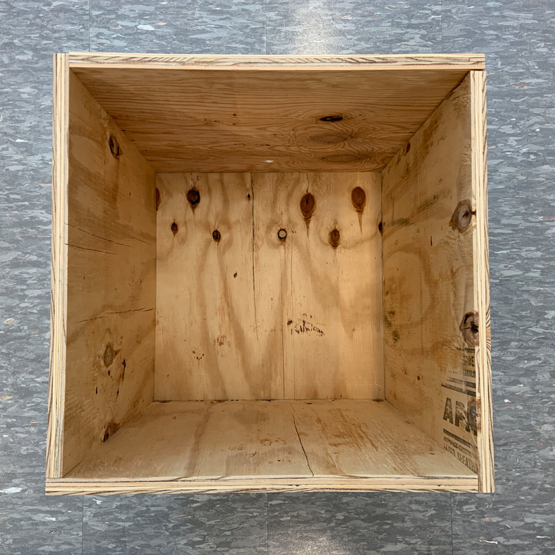
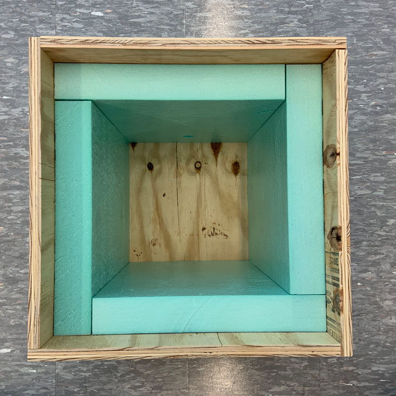
Waste was unavoidable when cutting pieces of rigid foam insulation, which provides thermal insulation for and a vapor barrier around the test environment. The pieces were cut on a table saw from a surplus sheet obtained from the fabrication lab at no cost. As was the case for the plywood shell, the four identical side pieces were arranged in a pinwheel configuration. The square bottom piece would nest between the sides, while the larger top piece would be attached to the underside of the lid and overlap the sides.
Before installation, a 5/8 inch hole was drilled through one of the side pieces to match the water vapor inlet hole in the plywood shell. The side pieces were installed first, and then the bottom piece was pushed through the space between them. The fit was tight, so no adhesive was required.
|
|
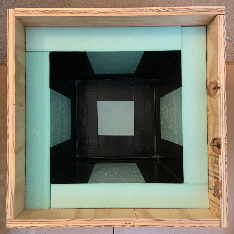
Flashing tape, which is commonly used to seal vapor barriers around doors and windows during building construction, was applied to the interior edges of the rigid foam insulation. This tape prevents water vapor from escaping the test environment through the gaps between adjacent pieces of insulation and being absorbed by the plywood shell instead of the wood sample under test.
|
|
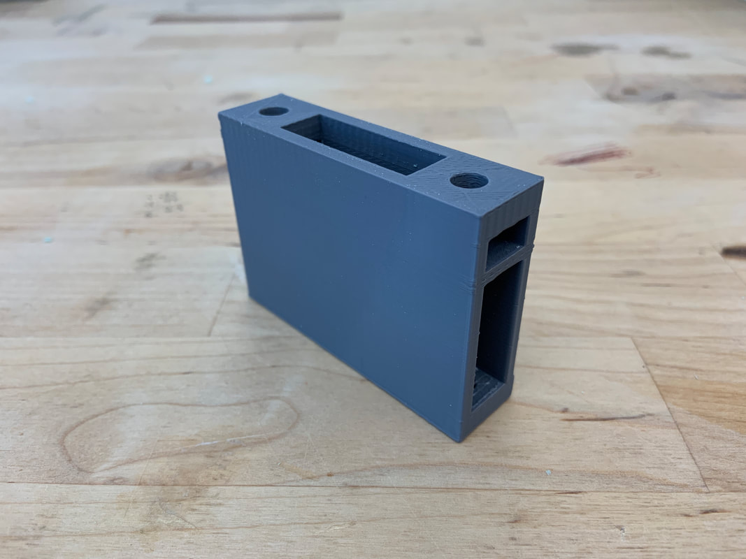
Sensor Mount
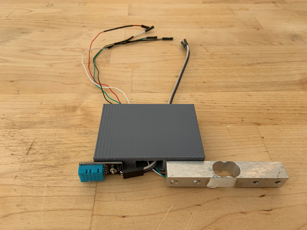
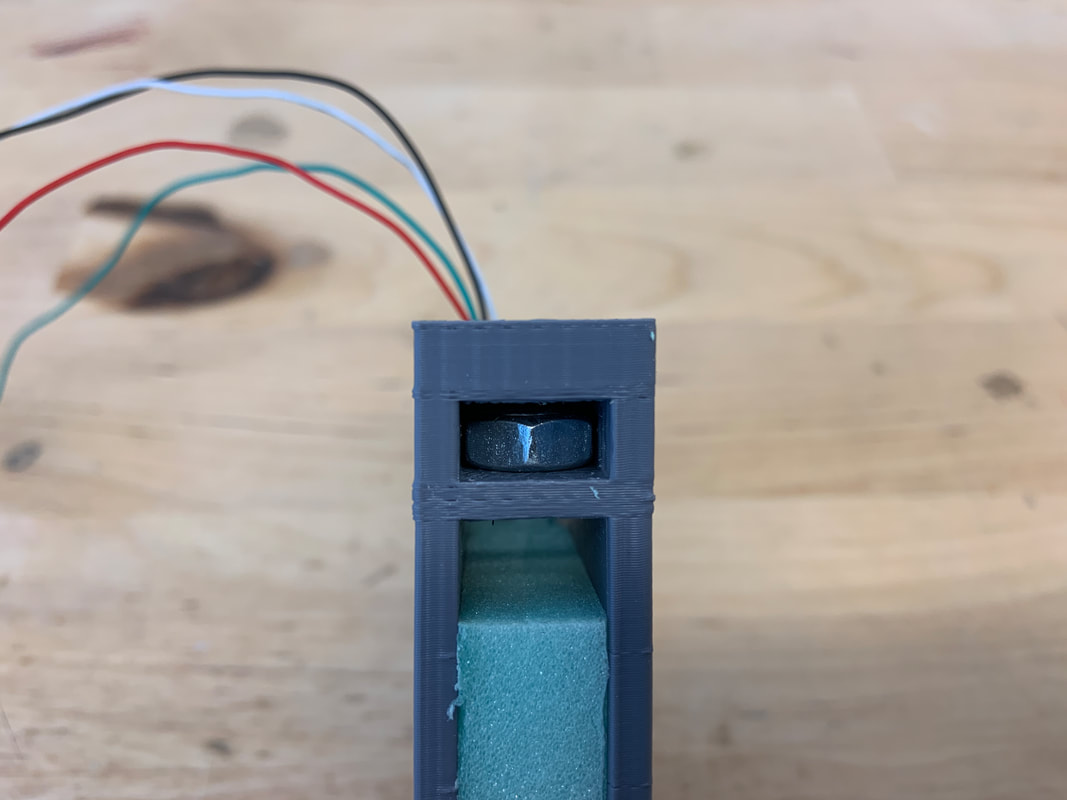
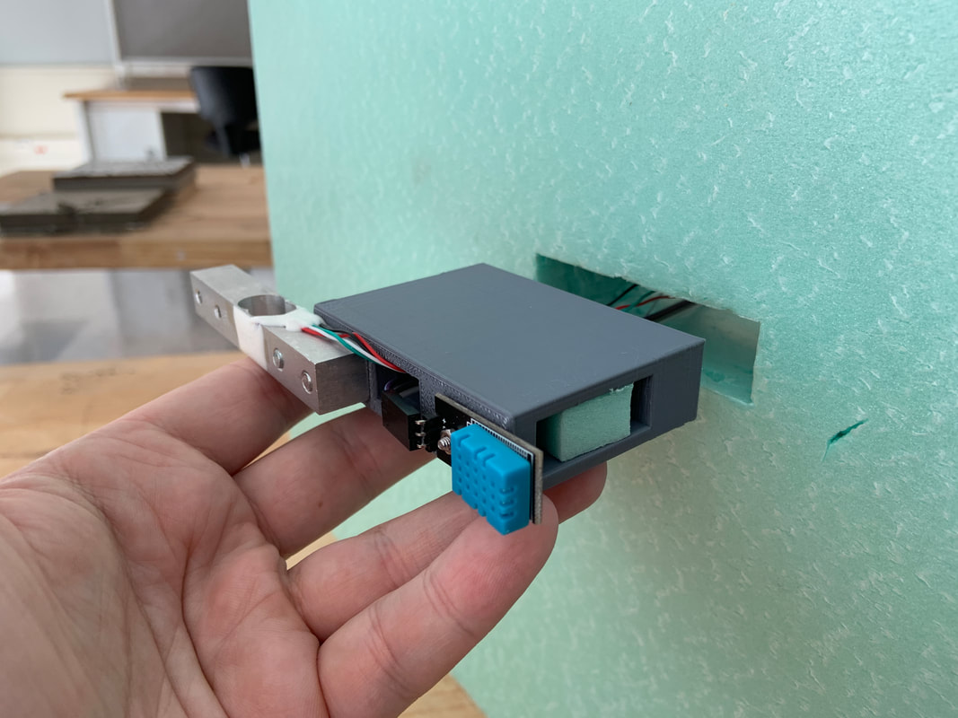
A mount was designed to securely and rigidly attach the load cell and the DHT11 temperature and humidity sensor to the plywood shell of the lid of the test enclosure. The load cell was attached to the mount with a pair of M5 machine screws, and the DHT11 with a single M2.5 machine screw. The mount was then attached to the plywood with a pair of 1/4" machine screws. Two small pockets were included in the design of the mount to hold the nuts in place while it was being secured to the plywood. The mount is 3 inches long, 3/4 inch wide, and 2 1/8 inches tall and was 3D printed in the fabrication lab at a cost of $3.
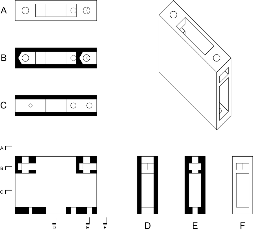
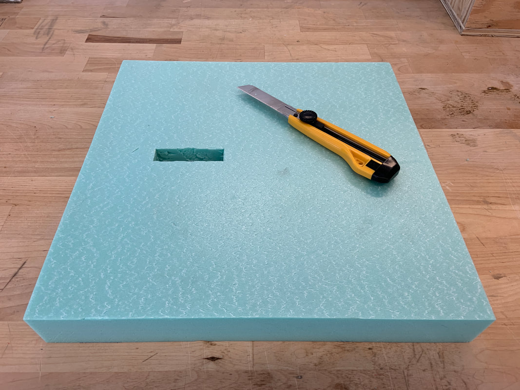
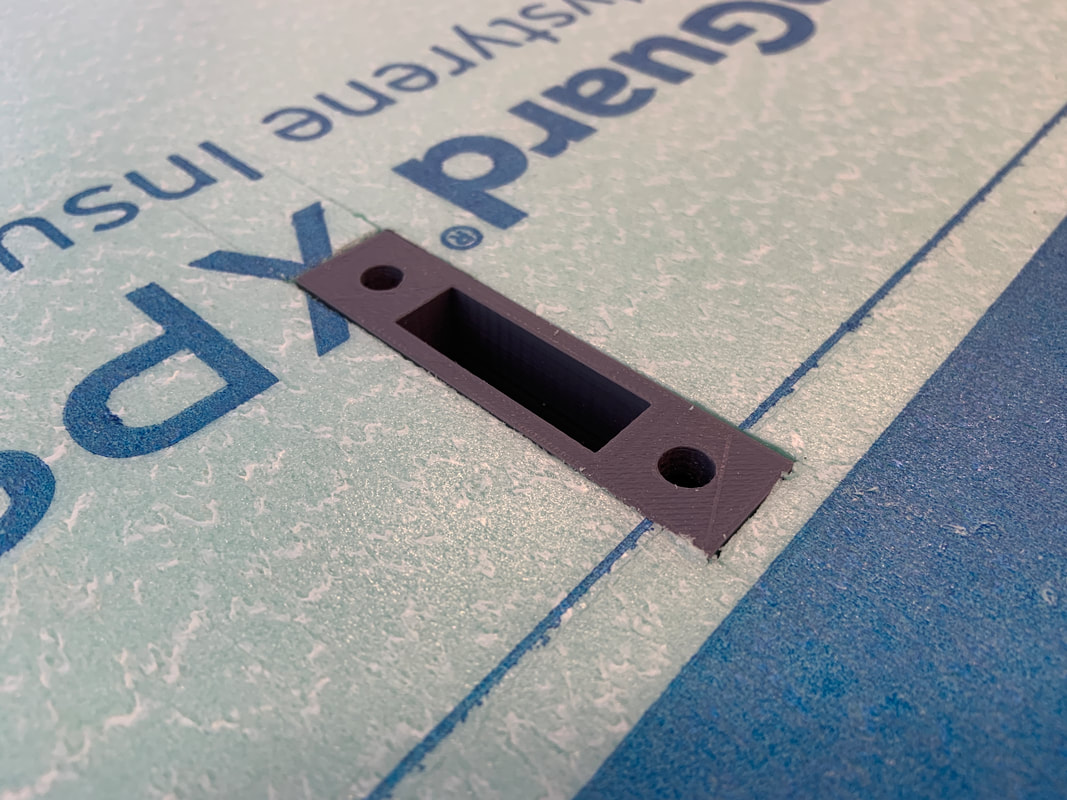
After the mount was printed, a pair of 1/4 inch holes were drilled through the plywood of the lid such that an object hanging from the end of the load cell would be roughly centered within the test enclosure. A 1/2 inch hole was drilled between them to permit the passage of wires between the sensors on the interior of the box and the Arduino on the exterior. Based on the position of these holes, an opening was manually cut through the top piece of rigid foam insulation to accept the mount.
After the sensors were attached to the mount, their wires were routed through its interior cavity. That cavity was then filled with scraps of rigid foam insulation to prevent heat and moisture from escaping the test enclosure. Finally, the mount was inserted into the insulation layer and screwed to the plywood shell.
After the sensors were attached to the mount, their wires were routed through its interior cavity. That cavity was then filled with scraps of rigid foam insulation to prevent heat and moisture from escaping the test enclosure. Finally, the mount was inserted into the insulation layer and screwed to the plywood shell.
|
|
|
Control System Hardware
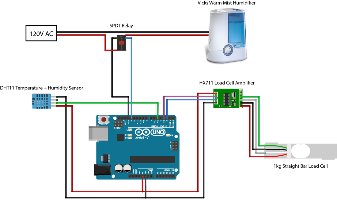
The control system for the test enclosure consists of the following electronic components:
Once pin connectors were soldering to the HX711 board and the ends of the load cell wires, the components were connected according to wiring diagram shown below.
- An Arduino Uno microcontroller that reads data from the sensors and regulates the humidity. The Arduino was included in the electronics kit provided to each student at the beginning of the semester.
- A DHT11 temperature and humidity sensor that measures the dry bulb temperature and relative humidity inside the test environment. The DHT11 was included in the electronics kit provided to each student at the beginning of the semester.
- A 1kg straight bar load cell that measures the weight of the wood sample under test. Liz obtained the load cell for approximately $4.
- An HX711 load cell amplifier that makes the signals from the load cell, which are too weak to be read directly by a microcontroller, easily readable by the Arduino. This tiny board was packaged with the load cell.
- An IOT Relay that controls the flow of electricity to the humidifier. This product, on load from Liz, contains single-pole double throw (SPDT) relay that allows digital control of a standard 120V power supply.
- A Vicks Warm Mist Humidifier that produces water vapor to increase the humidity of the test environment. The humidifier was borrowed from Liz's collection of such devices.
Once pin connectors were soldering to the HX711 board and the ends of the load cell wires, the components were connected according to wiring diagram shown below.
Control System Software
The control system code that was loaded into the Arduino (reproduced below) collects readings from the sensors and outputs them to the serial monitor as a line of tab-separated values approximately every 5 seconds. The load cell is powered down between readings to mitigate thermoelectric effects that could distort the load cell's readings.
The code also tracks an exponential running average, which minimizes random fluctuations, of relative humidity readings in the test environment. When the average drops below 75%, the humidifier is turned on to increase the moisture level of the test environment. When the average rises above 75%, the humidifier is turned off to prevent over-humidifying the environment, which could result in condensation and damage to the sensors.
The code also tracks an exponential running average, which minimizes random fluctuations, of relative humidity readings in the test environment. When the average drops below 75%, the humidifier is turned on to increase the moisture level of the test environment. When the average rises above 75%, the humidifier is turned off to prevent over-humidifying the environment, which could result in condensation and damage to the sensors.
#include <Adafruit_Sensor.h>
#include <DHT.h>
#include <DHT_U.h>
#include "HX711.h"

#define DHT_PIN 5
#define DHT_TYPE DHT11

DHT_Unified dht(DHT_PIN, DHT_TYPE);

#define RELAY_PIN 13
#define RELAY_THRESHOLD 75

#define LOADCELL_DOUT_PIN 2
#define LOADCELL_SCK_PIN 3
#define LOADCELL_OFFSET = 0
#define LOADCELL_SCALE = 1

HX711 loadCell;

float alpha = 0.25;
float movingAverage;
char humidifierState;


float getTemperature() {
  sensors_event_t event;
  dht.temperature().getEvent(&event);
  return event.temperature;
}

float getHumidity() {
  sensors_event_t event;
  dht.humidity().getEvent(&event);
  return event.relative_humidity;
}

void setup() {
  Serial.begin(9600);
  dht.begin();
  loadCell.begin(LOADCELL_DOUT_PIN, LOADCELL_SCK_PIN);
  loadCell.set_offset(LOADCELL_OFFSET);
  loadCell.set_scale(LOADCELL_SCALE);

  pinMode(RELAY_PIN, OUTPUT);
  digitalWrite(RELAY_PIN, LOW);
  humidifierState = '0';

  Serial.println("Time (ms)\tRaw Load Cell Reading\tTemperature (°C)\tRelative Humidity (%)\tHumidifier Power");
}

void loop() {
  loadCell.power_up();

  if (loadCell.wait_ready_timeout(1000)) {
    long loadCellReading = loadCell.get_value(10);
    float temperature = getTemperature();
    float humidity = getHumidity();

    movingAverage = humidity * alpha + (1-alpha) * movingAverage;

    if (movingAverage > RELAY_THRESHOLD) {
      digitalWrite(RELAY_PIN, LOW);
      humidifierState = '0';
    } else {
      digitalWrite(RELAY_PIN, HIGH);
      humidifierState = '1';
    }

    Serial.print(millis());
    Serial.print("\t");
    Serial.print(loadCellReading);
    Serial.print("\t");
    Serial.print(temperature, 1);
    Serial.print("\t");
    Serial.print(humidity, 1);
    Serial.print("\t");
    Serial.print(humidifierState);
    Serial.println();
  }

  loadCell.power_down();
  delay(5000);
}
Test Samples
Parts & Pieces
This section may not be applicable to all projects. Document any 'finishing touches' you included in your project.
Proposal |
Background |
Construction |
Methodology |
Results |