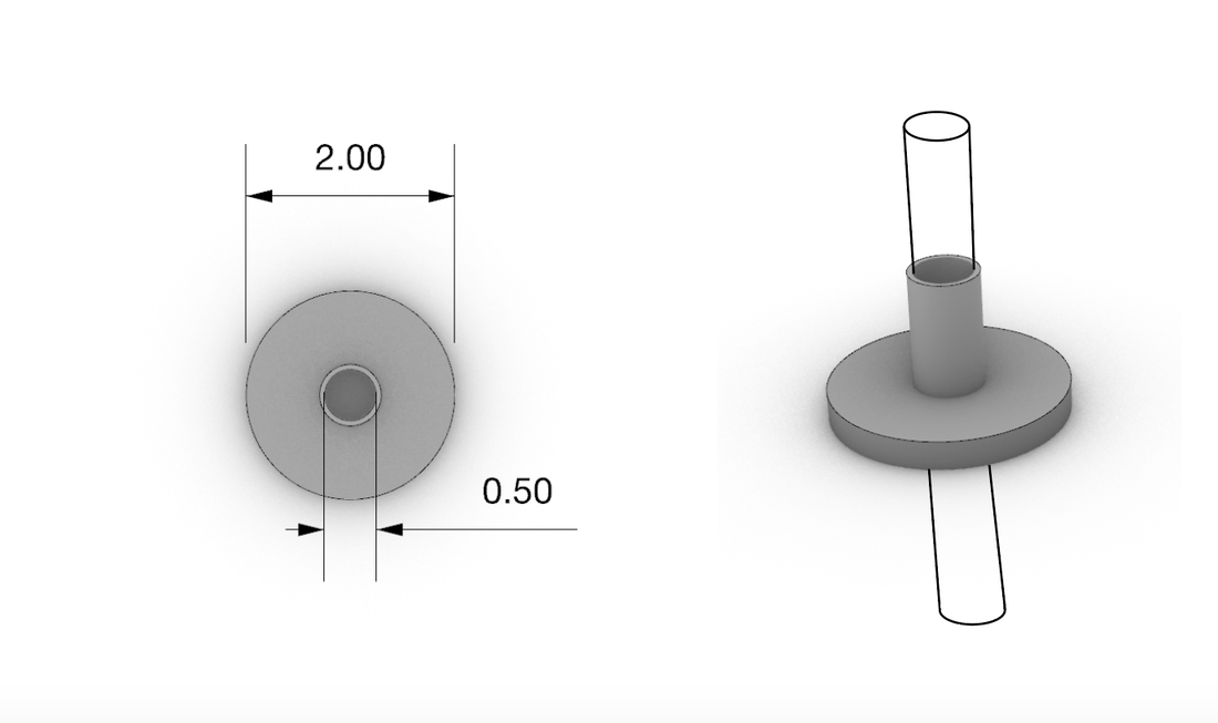
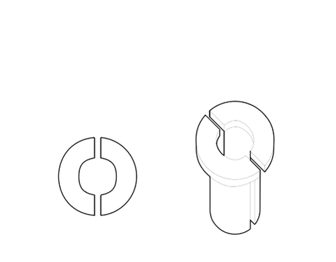
Construction Method
This is the proposed construction method for putting together the desiccant motor. In our recent studies it seems as though using the wheel is most efficient for surface area and depth in regards to the desiccant material. The image above represents the places where we will drill holes to be able to put the individual wedges into the inner circle. These inner wedges are used to hold the sheet metal in place, that will ultimately hold the desiccant material.
Materials/Budget
|
- Foam Insulation ($12.50)
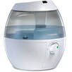
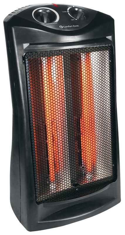
- Plywood (around $11) - humidifier ($14.99) - DhT11 Sensors and Breadboard ($90) - Heater ($15) - Fan (already have) - Tyvek wrap ($69.00) TOTAL: around $212.49 |


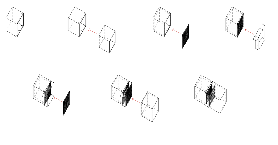
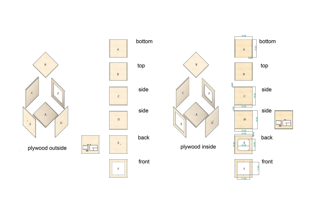
Enclosure Design
|
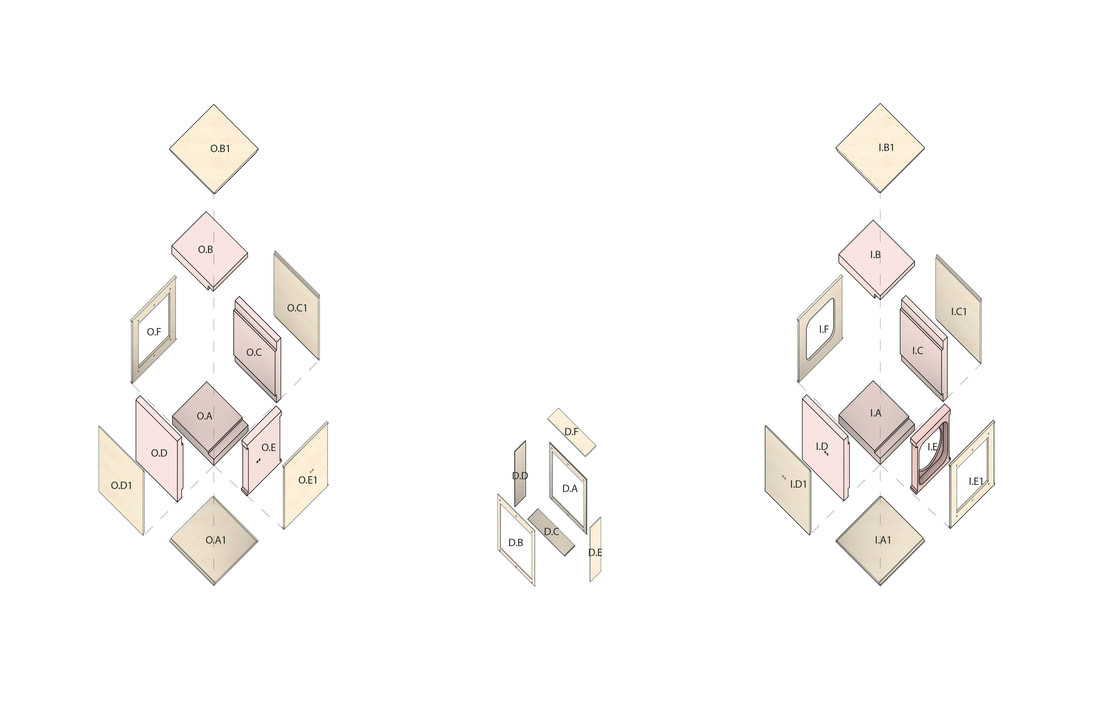
Plywood Design The images on the left depict both the inside environment box and outside environment box parts and assembly. Both are made form a 1/2" plywood sheet. sealing will be used to ensure minimal bridging. These cuts will be produced from the CNC machine |
|
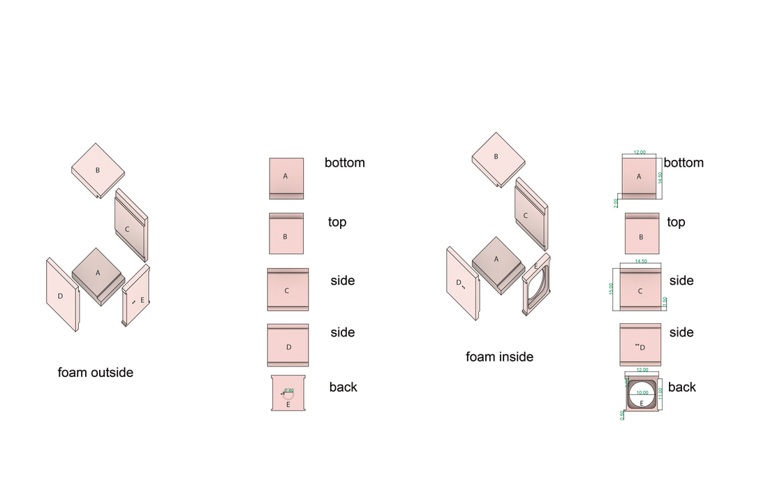
Foam Design The images on the left depict both the inside environment box and outside environment box parts and assembly. Both are made form a 1" foam sheet. these cuts will be produced from the CNC machine. |
Rhino File:
Attached below is the Rhino file for producing the cut files. |
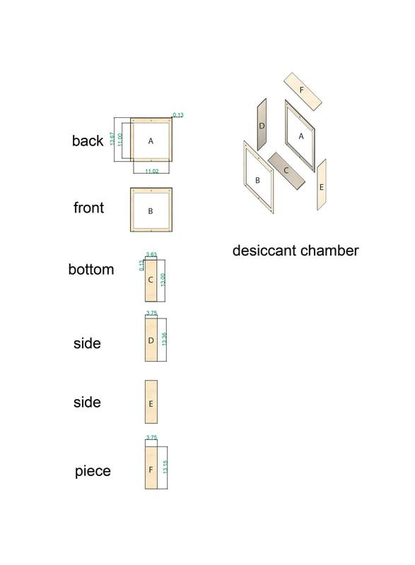
Desiccant Chamber The images on the left depict the integrated mesh chamber for the desiccant material. Made out of 1/8'' plywood, the cuts will be made from the laser lab and the fabrication lab. the mesh screen will be stapled to the inside perimeter of the chamber for effective sealing. |
| buildtestmodel.3dm |
Controls (electronics)
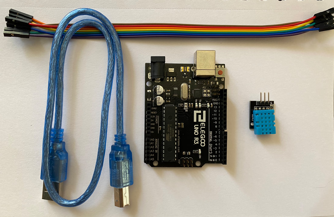
Project components:
• Arduino Uno (figure 1)
• DHT11 temperature and humidity sensor (figure 2)
• USB cable (figure 3)
• male to female Jumper cables (figure 4)
• DHT11 temperature and humidity sensor (figure 2)
• USB cable (figure 3)
• male to female Jumper cables (figure 4)
Setting up Arduino Desktop IDE

Launching The ProgramDownload and install the Arduino operating system to your desktop, when completed, use the USB cable and the Arduino uno and plug those into your computer. The USB cable along with your desktop will provide sufficient power to start up Arduino uno. The indication that it is on and working properly will be the green LED light will turn on next to the power symbol. When this is up and running open the IDE and start the process to set up your code:
Tools > Board > Arduino/Genuino Tools > Port > /dev/cu.usbmodemXXXX (the 4-5 numbers at the end are custom to the device). 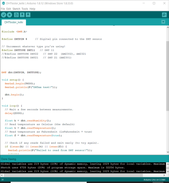
|
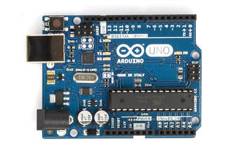
Figure 1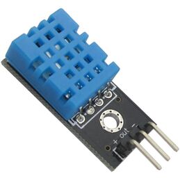
Figure 2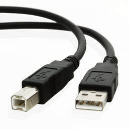
Figure 3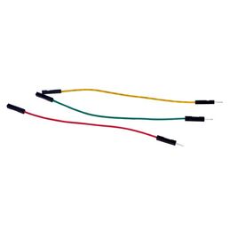
Figure 4Test Code
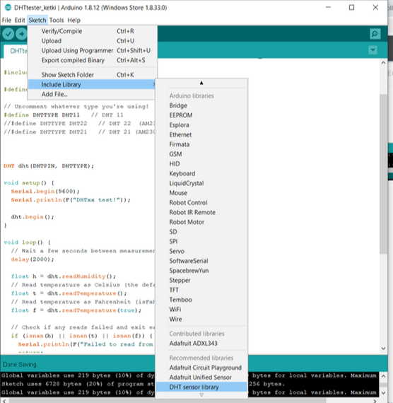
Download and install the DHT11 code example from the Arduino data library (this should be installed from the first initial download). Follow the instructions and make sure they are located in the correct folder. Examples > DHT Sensor Library > DHTtester Open the serial monitor to see readings (Tools > serial monitor). when open go to sketch > include library > DHT sensor library > then, press verify to make sure the code is ready > upload to save to your code data. This is a helpful link for troubleshooting: http://www.arduino.org/learning/getting-started/getting-started-arduino-uno |
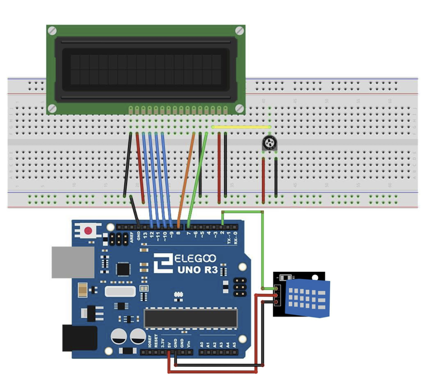
Circuit Diagram (relay DHT11)
First, Grab the Adruino Uno, 3 male to female jumper wires, and the DHT11 sensor:
• The red male to female jumper wire, (or color of your choice) should go into the last left-hand port (facing you) and be connected into Adruino port slot 4
• The blue male to female jumper wire, (or color of your choice) should go into the middle port of the DHT11 sensor and be connected into Arduino port GND on the right hand side facing you.
• The Green male to female jumper wire, (or color of your choice) should go into the right-hand port (facing you) of the DHT11 sensor and be connected into Arduino port 5V on the right hand side facing you.
•
To connect your DHT11 Temperature and Humidity sensor to the Elegoo Uno R3 follow the diagram and instructions above. One you have set it up and plugged in into the computer, use the code below to start collecting data
|
DHT11 Code
LCD Intro Code
Example Chart:
Below is a estimated example of how data can be configured from the out put of data. 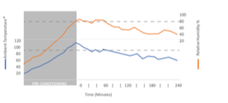
|
Parts & Pieces
|
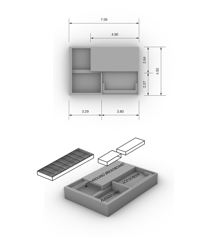
Custom Housing This version of custom housing is for our breadboard, Elegoo Uno, and LCD Screen. This would go on the back of our set uo and the breadboard would be at the top and has a slot for it to slide into. There is the custom fit spots for both the Uno and the screen. This is a compressed setup for our controls and data setup. This housing would be 3-D printed. |
|
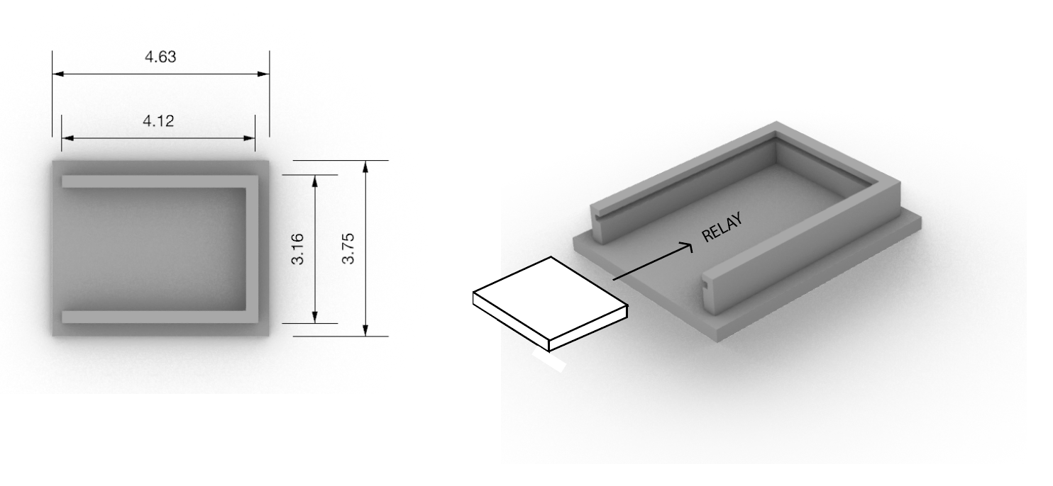
Custom Housing: Relay This holds the relay and is separate from the controls above. The relay would be covered by acrylic that slides into the grooved slot in the print. The housing would be 3-D printed. |
|
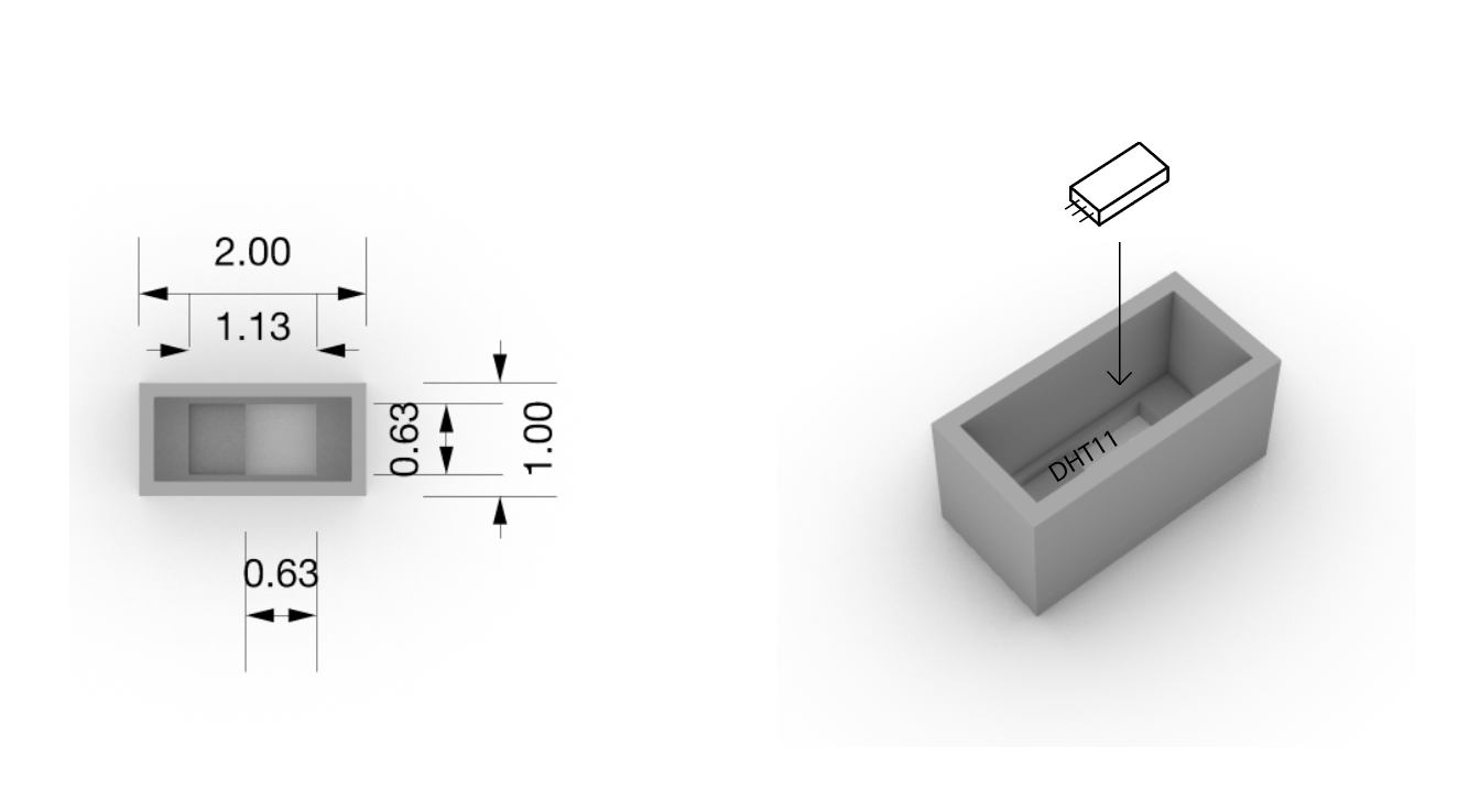
DHT11 Housing This is the temperature and humidity sensor housing. It is fit so that the sensor will be exposed out the hole in the back but is fit to where the sensor fits perfectly and will not fall out. This housing will be 3-D printed |
|
Humidity Cap This piece will go over the hole and the humidifier tubing so that the hummer will add moisture into the box without having any escape. This is 3-D printed. Wire Plug The wire plug is used to cover any holes where wiring or tubes go into the boxes. This keeps air from escaping and messing up data collection. This is 3-D printed. |