Enclosure Design
The basic enclosure consisted of a 25"x16"x12" box. The sides and top of the box were constructed using clear polycarbonate plastic and the base was constructed from scrap plywood with divots approximately 1/7 inches thick - these divots were just wide and deep enough to secure the polycarbonate frame. A detachable design was chosen so the polycarbonate enclosure could be lifted from the base to allow for the mesh frame to be adjusted from within the chamber, as well as allowing for the interior to be dried between tests
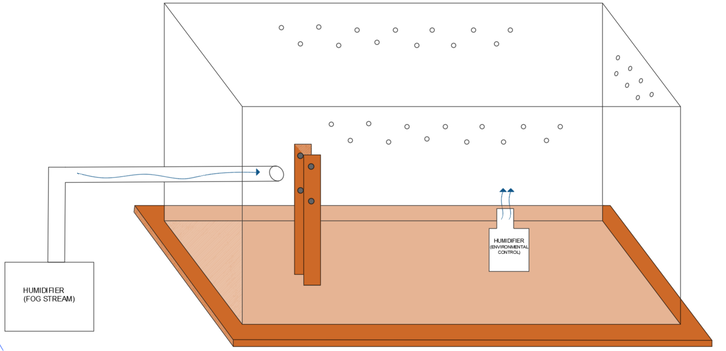
Figure 1. Diagram of initial prototype (Trials 1-3)
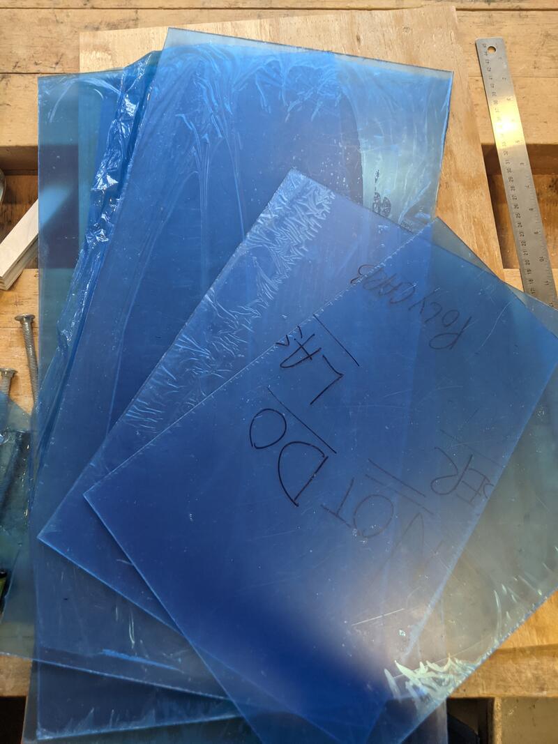
Figure 2. Freshly cut polycarbonate that made up the enclosure of the environmental chamber
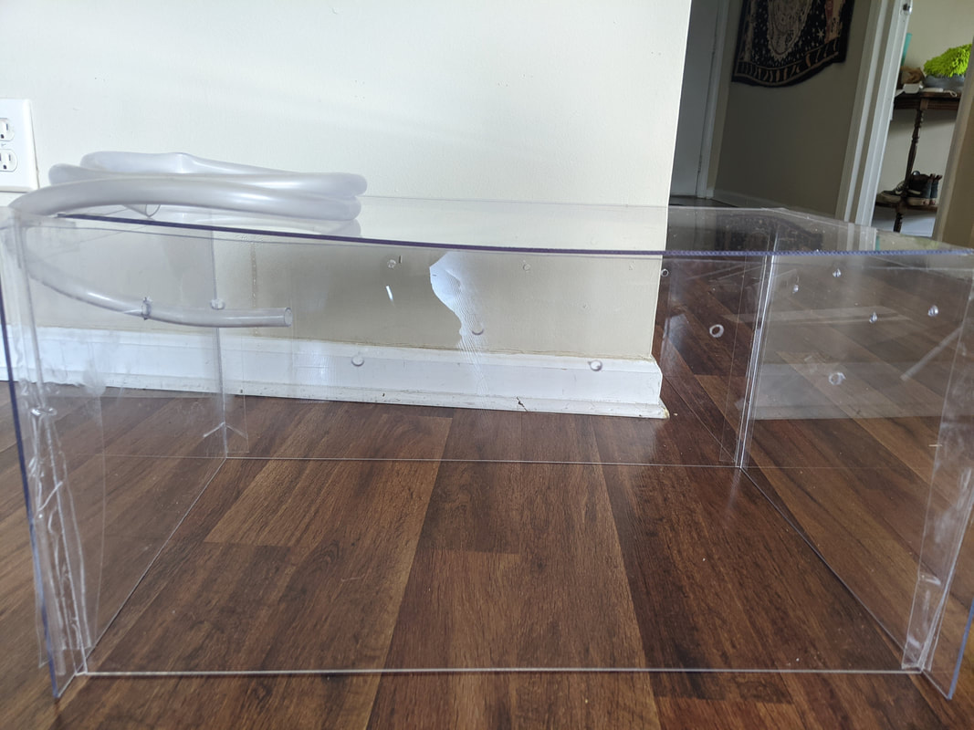
Figure 4. Initial enclosure prototype (side view)
|
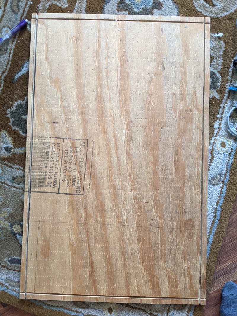
Figure 3. Plywood base of environmental chamber containing 1/7" deep divots to secure the polycarbonate enclosure
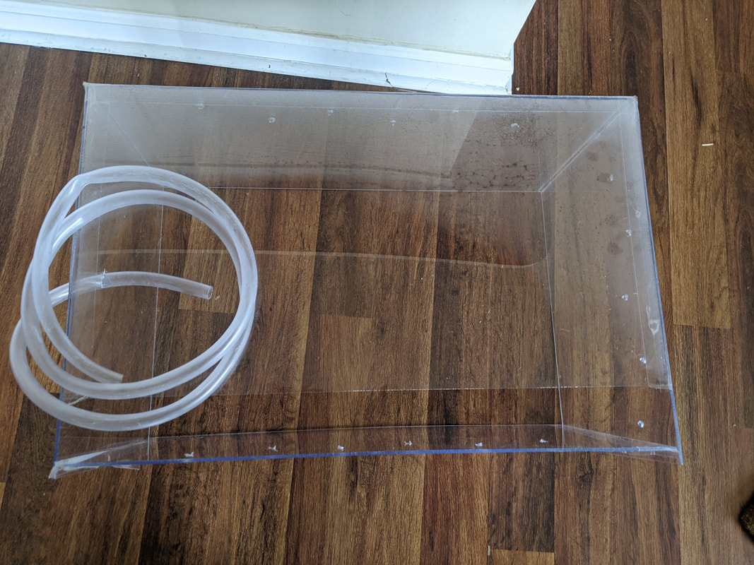
Figure 5. Initial enclosure prototype (top view)
|
Ventilation holes (5/16") were drilled into the sides of the polycarbonate, spaced 3", to achieve 100% relative humidity and consistent temperature within the box without the buildup of condensation. Ventilation was further promoted via a 3" gap on the top of the box.
An additional hole (1/2") was drilled into the far side of the box to allow for the tube connected to the second humidifier to be passed through.
Controls (electronics)
Arduino software programmed into an Elegoo Board was used to monitor the internal conditions of the environmental chamber. Controls included an LCD sensor display that was used alongside a combination humidity/temperature sensor (DHT-22) to observe changes in real time. To produce accurate results, the experiment required that uniform preconditioning requirements be maintained throughout all tests. To reduce further discrepancies the sensor was secured to the environmental chamber in the same position for each trial.
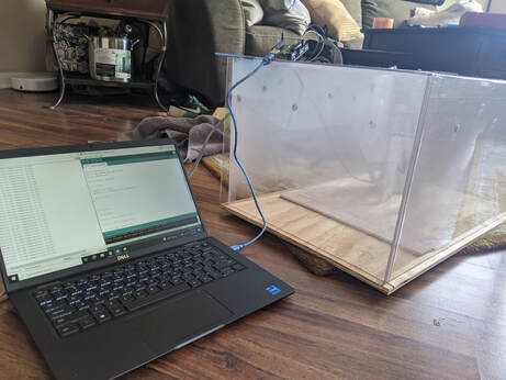
Figure 6. Initial electronic control setup for initial prototype (DHT-11 temp/humidity sensor only)
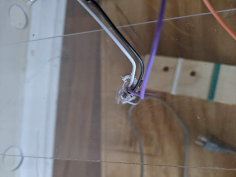
Figure 8. Support structure/electronic inlet for environmental chamber (closeup)
|
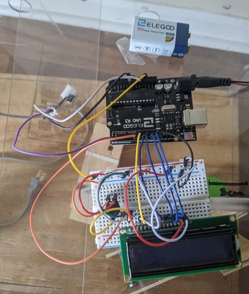
Figure 7. Final electronic control setup for final prototype (DHT-22 temp/humidity sensor and LCD Sensor Display)
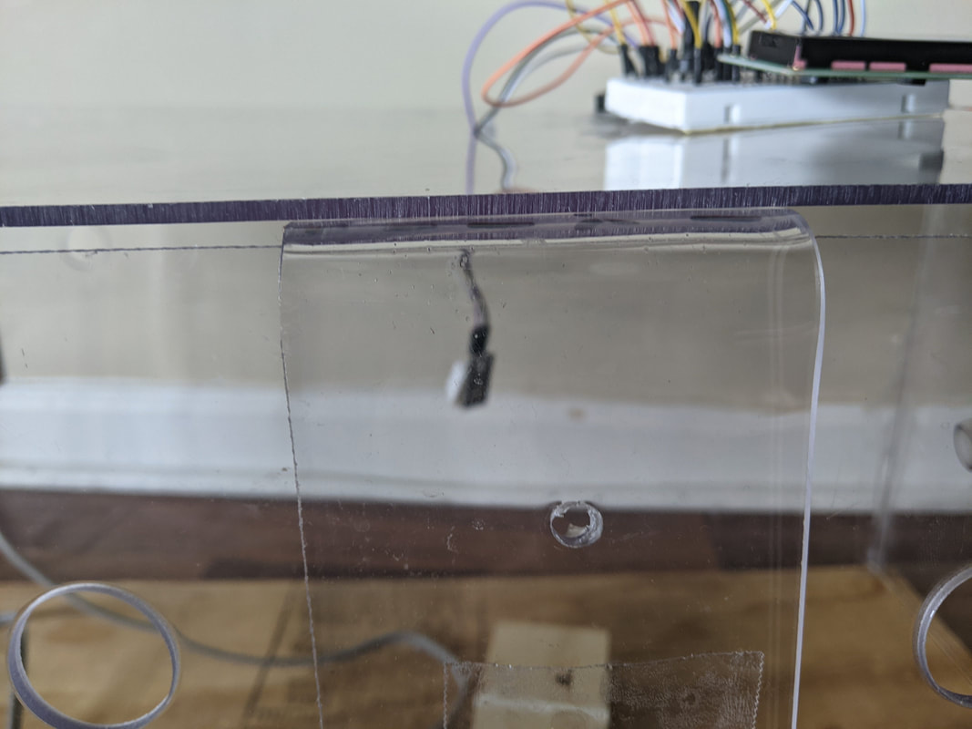
Figure 9. Support structure/electronic inlet for environmental chamber (wide shot)
|
The experiment conditions were monitored using a combination humidity/temperature sensor (DHT) and the LCD sensor display via the following code:
Code Editor
Parts & Pieces
An array was created by drilling two ¼ inch threaded bolts, spaced 2 inches apart vertically, into thin plywood (9"x2"). Stainless steel wire was then woven between the bolts to create a dual-layer vertical mesh.
Additional slits were drilled into these pieces to represent contact angles of 60 and 45 degrees. These slits were meant to be supported by an additional piece of plywood placed vertically inside the box to allow for the contact angle to shift easily.
Additional slits were drilled into these pieces to represent contact angles of 60 and 45 degrees. These slits were meant to be supported by an additional piece of plywood placed vertically inside the box to allow for the contact angle to shift easily.
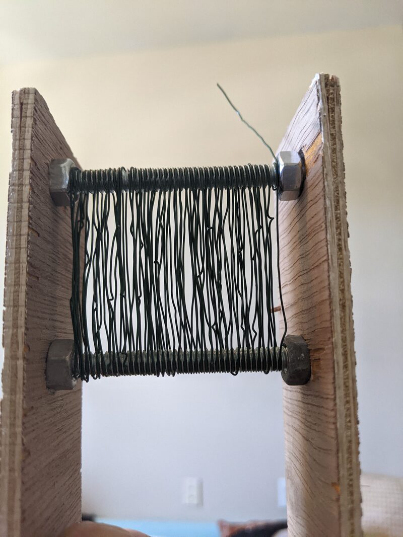
Figure 10. Vertical mesh created by weaving flexible stainless-steel wire through threads of bolts.
|
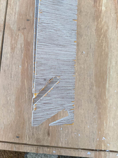
Figure 11. Original frame/base support structure (Trials 1-3)
|
Control Conditions
Two humidifiers were utilized in conducting these tests. The first humidifier was placed inside the environmental chamber to create consistent internal conditions of 95-100% relative humidity and a temperature of 24.5C (+- 0.1C). The second humidifier was connected to the ½ inch tube placed in front of the vertical mesh to represent a fog stream.
The dimensions of the array were intentionally chosen to be only slightly larger than the tube distributing the fog stream. This allowed for the entirety of the fog stream to pass through the mesh with limited variability. In contrast, the environmental chamber enclosure was designed to be significantly larger in proportion to the net so the internal conditions could be more easily maintained. Use of a humidifier inside a smaller chamber would likely cause temperatures and pressure inside to rise far more quickly, requiring further ventilation and monitoring to maintain the required consistent internal conditions throughout the tests.
The dimensions of the array were intentionally chosen to be only slightly larger than the tube distributing the fog stream. This allowed for the entirety of the fog stream to pass through the mesh with limited variability. In contrast, the environmental chamber enclosure was designed to be significantly larger in proportion to the net so the internal conditions could be more easily maintained. Use of a humidifier inside a smaller chamber would likely cause temperatures and pressure inside to rise far more quickly, requiring further ventilation and monitoring to maintain the required consistent internal conditions throughout the tests.
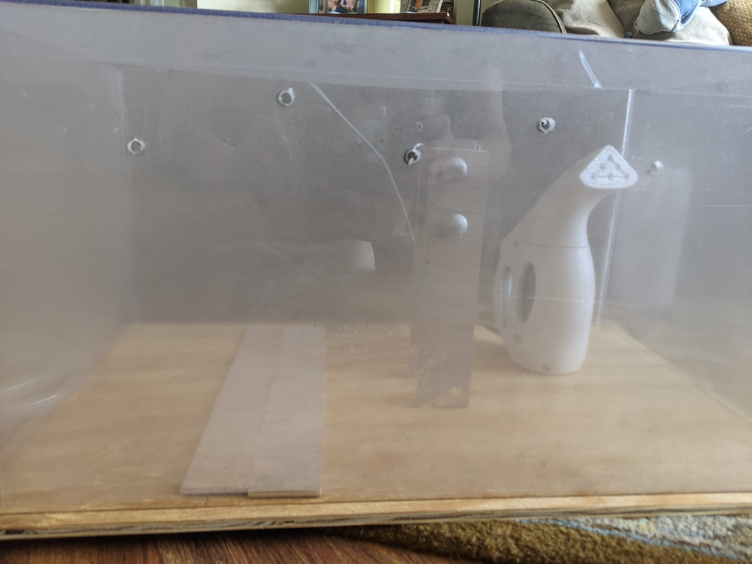
Figure 12. Initial prototype reaching preconditioning requirements (side view)
|
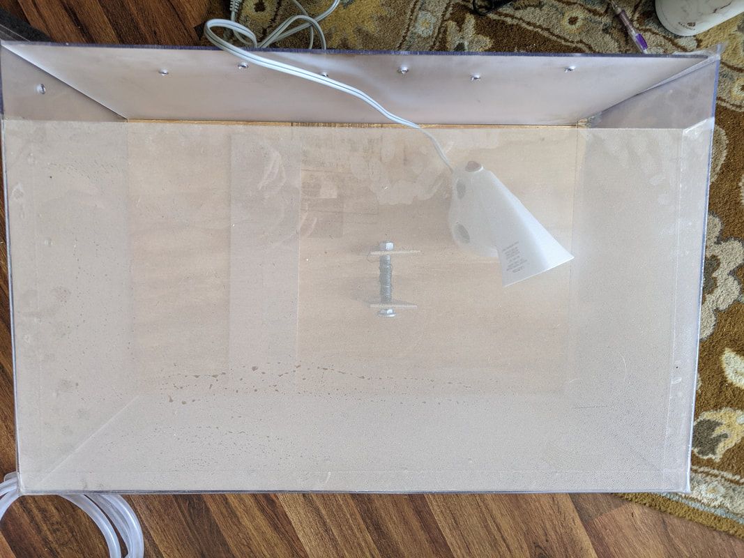
Figure 13. Initial prototype reaching preconditioning requirements (top view)
|
Tweaks and Changes
Upon completing the first round of tests on this device it became clear that attaching the frame to the base via precut slits did not provide adequate support during experimentation. Because of this the frame was redesigned to be held to its base via bolts and pre-drilled holes. Each of these holes represented different contact angles for the net.
Figures 14 and 17represent the design used to test for the first three trials. This initial design of the environmental chamber was ineffective due to inadequate ventilation and the frame was not sturdy enough to produce constant results. Based on trials 1-3 the following changes were planned for the updated prototype:
Figures 14 and 17represent the design used to test for the first three trials. This initial design of the environmental chamber was ineffective due to inadequate ventilation and the frame was not sturdy enough to produce constant results. Based on trials 1-3 the following changes were planned for the updated prototype:
- Increase size of ventilation holes to prevent excess pressure buildup.
- Construct sturdier frame capable of producing more accurate angles.
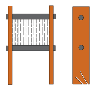
Figure 14. Original frame (Trials 1-3)
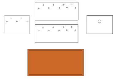
Figure 17. Environmental chamber components (Trials 1-3)
|
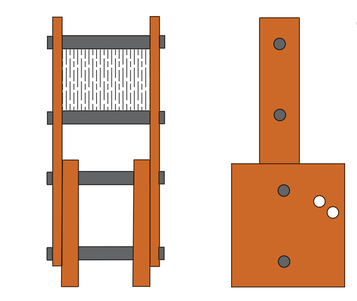
Figure 16. Frame redesign (Trials 4-9)
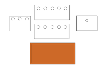
Figure 18. Environmental chamber components (Trials 6-9)
|
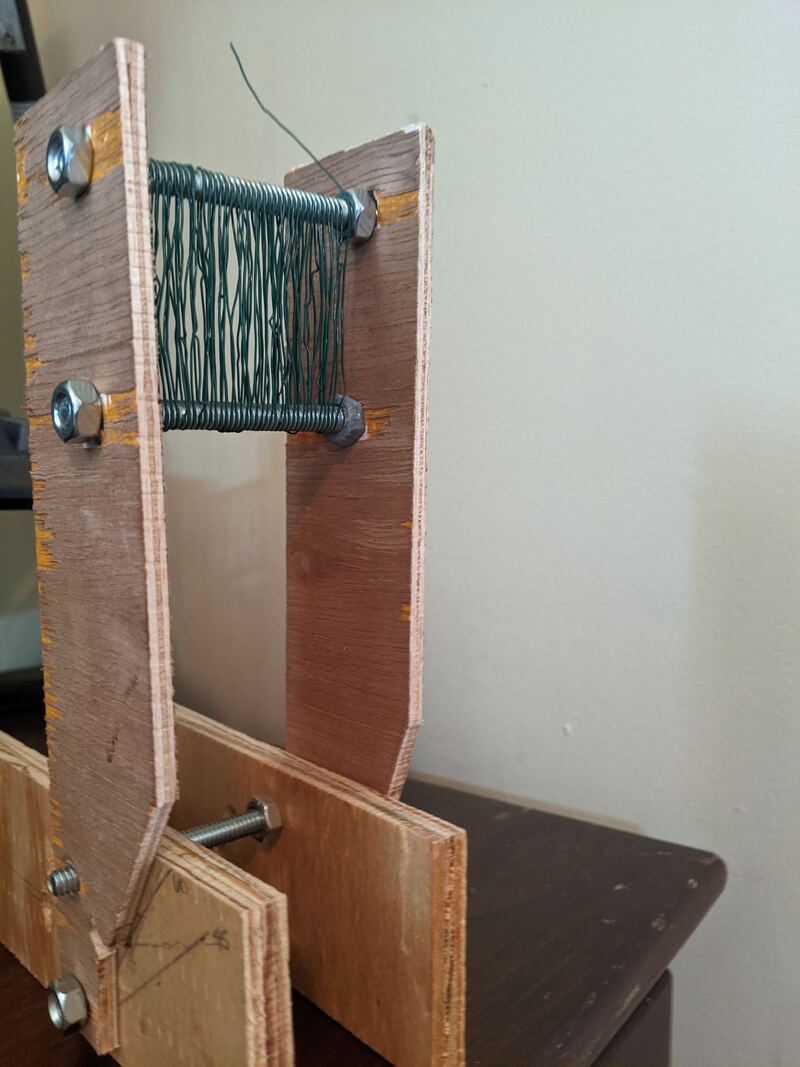
Figure 19. Redesigned base/support structure (front view)
|
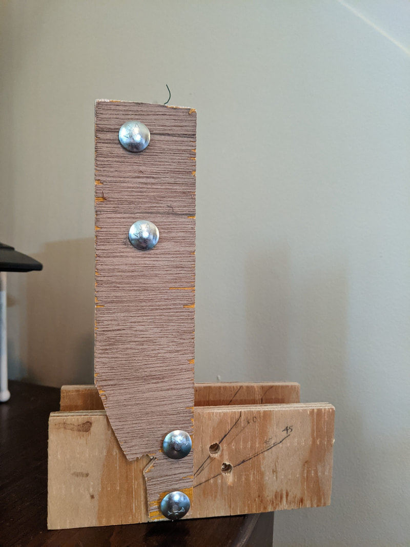
Figure 20. Redesigned base/support structure (side view)
|
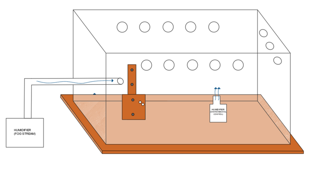
Figure 21. Diagram of prototype redesign
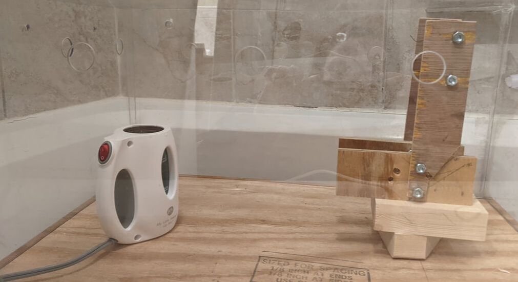
Figure 22. Revised prototype setup (increased ventilation and redesigned support structure)
|
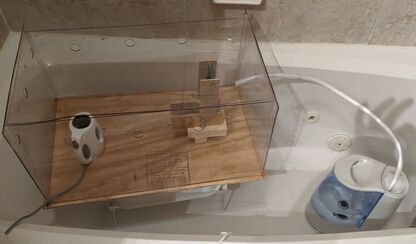
Figure 23. Revised prototype setup with fog stream humidifier (increased ventilation and redesigned support structure)
|
The prototype redesign seen in Figure 16, and Figures 18-23 represent the set of changes made to increase collection efficiency of device. The redesign replaced the angled slits on the base for a more secure and accurate dowel-based system and the ventilation holes were widened to 7/8".
Ventilation was promoted further by resting the lid of the enclosure on an additional narrow strip of polycarbonate that had been molded with a heat gun to curve into two “right angles” on each side. This strip was then positioned perpendicularly to the length of the box as shown in Figure 24 and Figure 26. The resulting gap provided additional ventilation, consistent throughout each test, that was effective enough to prevent the lid from warping due to high temperatures. The support strip also served as a support structure for the electronic monitoring controls as shown in Figure 25 and Figure 26.
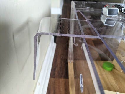
Figure 24. Image of molded "right" angle of support strip
Figure 25. Perpendicular support/ventilation structure for lid and electronic controls
|
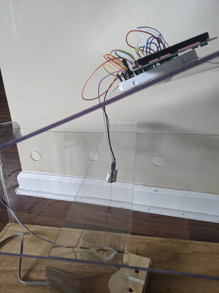
Figure 26. Image of perpendicular support without lid
|