Parts & Pieces
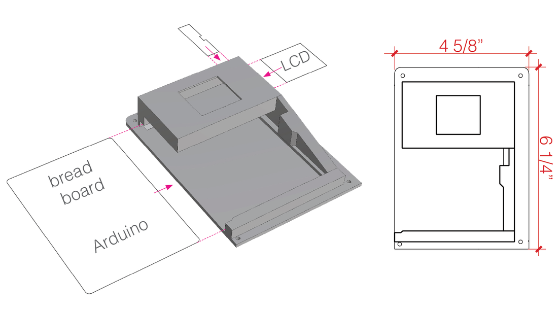
Figure 1
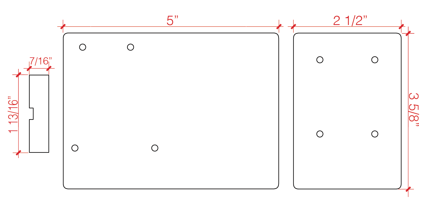
Figure 2
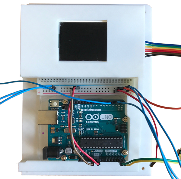
Figure 3
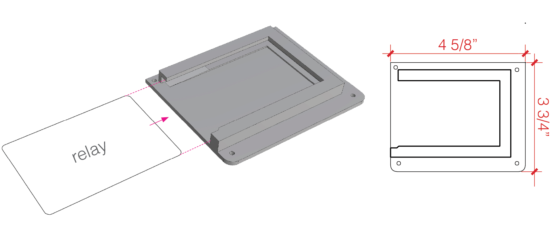
Figure 4
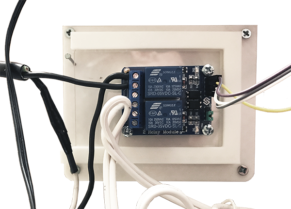
Figure 5
|
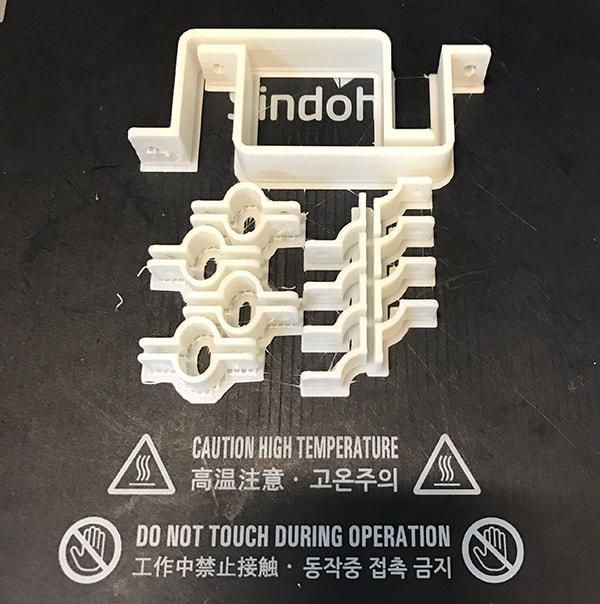
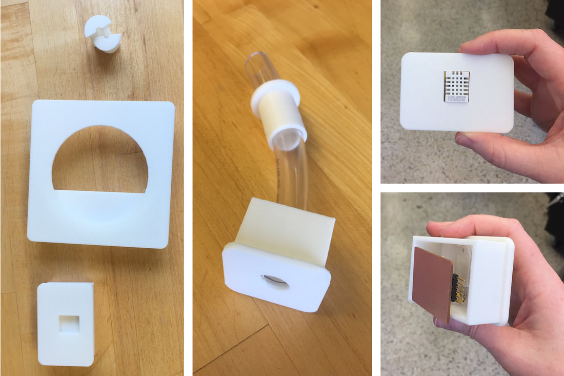
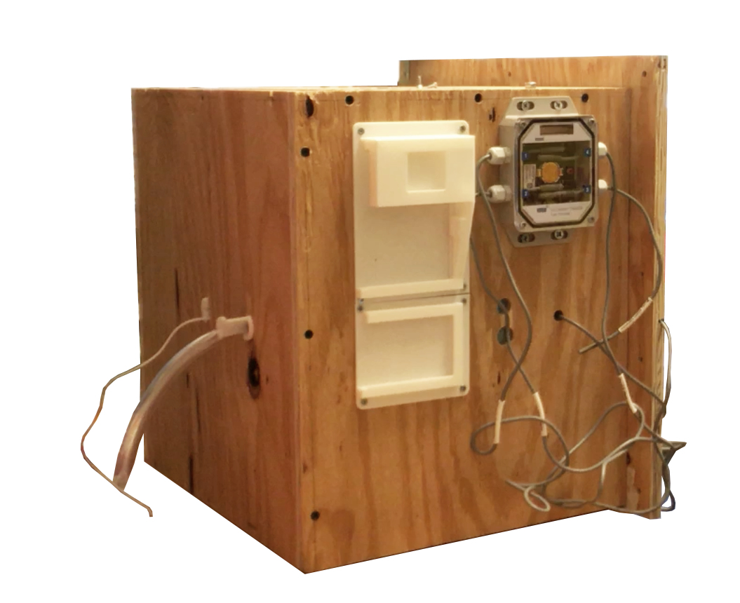
Most of these parts are custom designed and 3d printed using a 3dwox printer. The printer uses PLA plastic which worked well for prototyping but might need to be replaced with more permanent materials, especially when used near high temperatures.
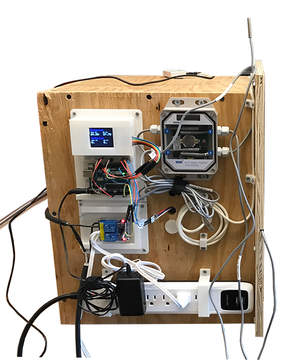
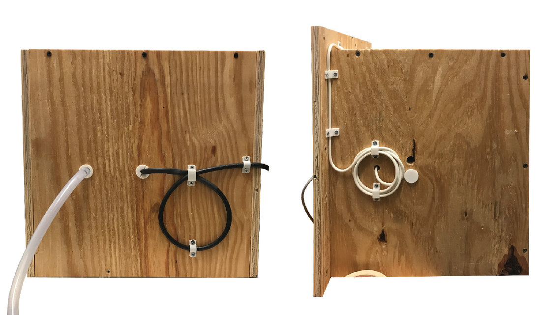
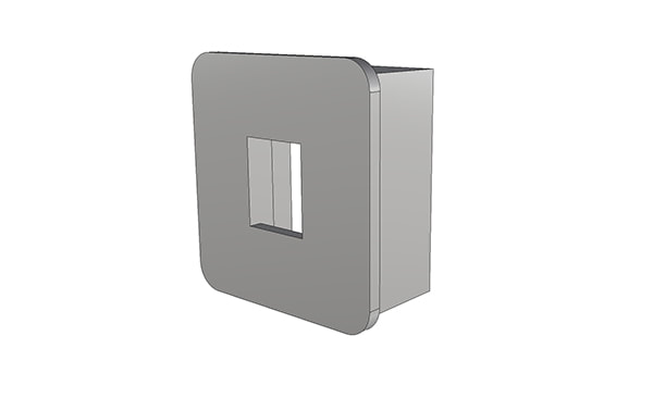
Custom Housing - Arduino This print took approximately 18 hours. Since the part has a number of pockets, support material was difficult to remove manually. It may be easier to use a 3d printer where support is dissolved off in a bath, such as the Stratsys Dimension Elite. Files: ARDUINO HOUSING.3dm ARDUINO HOUSING.Stl Arduino Backer Plate The breadboard specified comes with an acrylic backer plate and standoff screws, however you can lasercut your own using these dimensions on 1/8” clear acrylic. Use the same material to lasercut the relay backer plate and small panel for the Arduino housing above. Files: PLATES.3dm Arduino, Breadboard & LCD This casing both hides and protects the breadboard, yet maintains the flexibility of the parts. Only the power and ground rails are accessible as all data cables are plugged directly into the Arduino board. All of the parts are removable for further prototyping and future use. The LCD screen slides in and is secured by an acrylic panel (dimensions shown in Figure 58). The notch on the side of the small panel is important for easy removal of the part without damaging the printed housing. Custom Housing – Relay Similar to the Arduino housing shown above, the relay casing is 3d printed. The realy, attached to a separate acrylic backer panel, slides in from the side. This housing provides an added safety feature as it keeps the back of the relay board out of reach and away from combustible materials. File: RELAY HOUSING.3dm RELAY HOUSING.stl Custom Housing – Relay Here the relay is protected and secured, which is important given the large amounts of power flowing into this part. Power and data inputs are unobstructed. Housing in Place The photo below shows both 3d prints in place (as well as the hobo sensor, which was discussed earlier). Cable Management Wiring quickly became unruly, so it was helpful to 3d print wire routers to keep everything in place and organized. The photo shows the parts still connected to the 3d printer tray, including float support material. Similar parts are also available for purchase. The parts at the top of the image hold the surge protector in place while the parts on the bottom left constrain general wires and the parts at the bottom right constrain cables at corner conditions. Attach the parts to the box using small screws and make sure that screws do not puncture through the foam barrier. File: CABLES.3dm, CABLES.stl Cable Management Here are all the cables under control of the wire management parts on the hot box (Figure 63) as well as the back (Figure 64) which has inputs from the heater and humidifier. The cold box (Figure 65) has far fewer controls and consequentially far fewer wires, but a few of the holes needed to be plugged. Wire Plugs Some of the holes needed to be cut into the wood and foam larger than the wire so that parts could easily be fed through. This may lead to thermal bridging, so 3d print custom plug holes to minimize air transfer through openings. File: WIRE PLUGS.3dm WIRE PLUGS.stl Sensor Housing The sensor housing keeps the DHT22 sensor in place and keeps the wiring out of conditioned space. One is needed for each box. File: SENSOR-DHT22.3dm (.stl) Sensor Housing For the parts that hold sensors and systems in place, fill the empty space of the printed part with foam, cut either on the bandsaw or with a hot wire cutter. Humidifier Cap The humidifier cap directs the steam into the tubing, which pipes into the hot box. All parts are 3d printed. File: HUMIDIFIER.3dm (.stl) Humidifier Connections ½” vinyl tubing is used to pipe the humid air into the hot box. The 3d printed cap fits tightly into the humidifier (once the cap that comes with it is removed) and directs the steam into the tube. To keep liquid water from dripping into the hot box, the humidifier must sit below the openings. Lamp Holder The heat lamp holder is larger than it needs to be, as a hot plate was originally used as the heat source. It holds the lamp holder that the heat lamp screws into. File: HEATER.3dm (.stl) Heat Lamp Housing Fill the interior of the sensor housing with foam, allowing only minimal space for the wires to pass through. This is where the extension cables (from Figures 29,30) come in handy as the case would need to be much larger if jumper cables were used. The casing is designed so that openings are offset and air cannot pass direction through. |