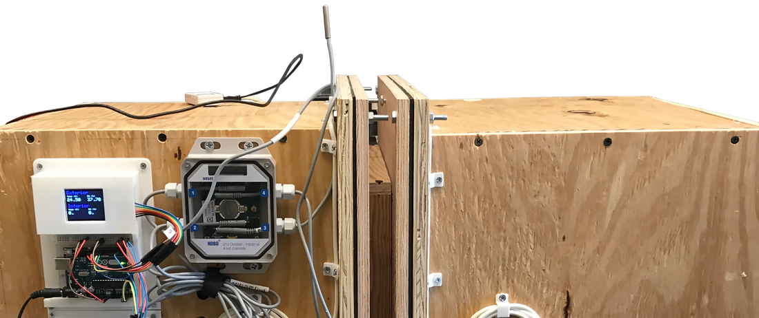
Enclosure Design
The core each chamber is constructed with 2” Extruded Polystyrene Foam (XPS). The material is affordable and easy to work with. XPS also offers a high R-value and resists moisture penetration, making it a suitable candidate for hygrothermal experiments. The box is then wrapped in 5/8” plywood for durability and attachment purposes.
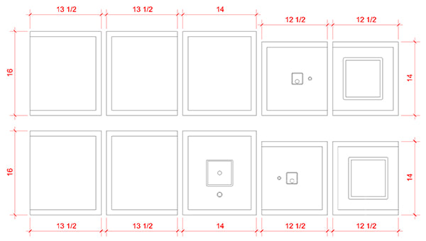
Figure 1
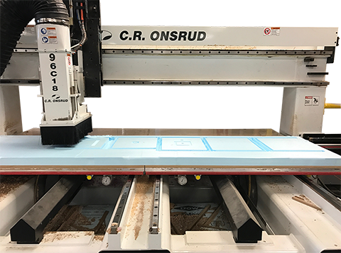
Figure 2
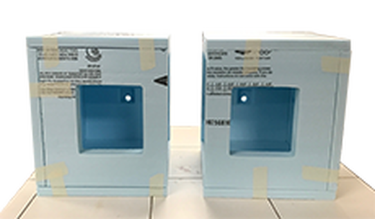
Figure 3
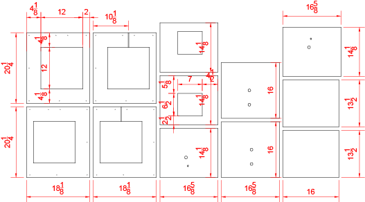
Figure 4
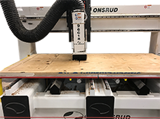
Figure 5
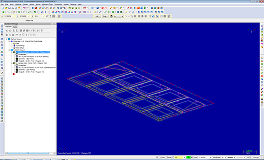
Figure 6
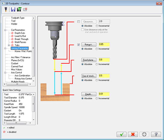
Figure 7
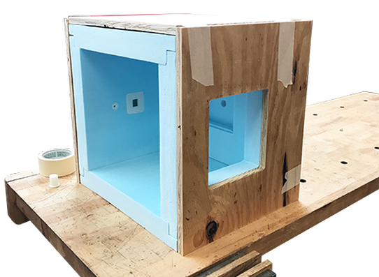
Figure 8
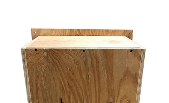
Figure 9
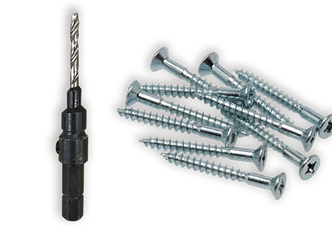
Figure 10
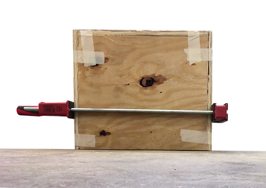
Figure 11
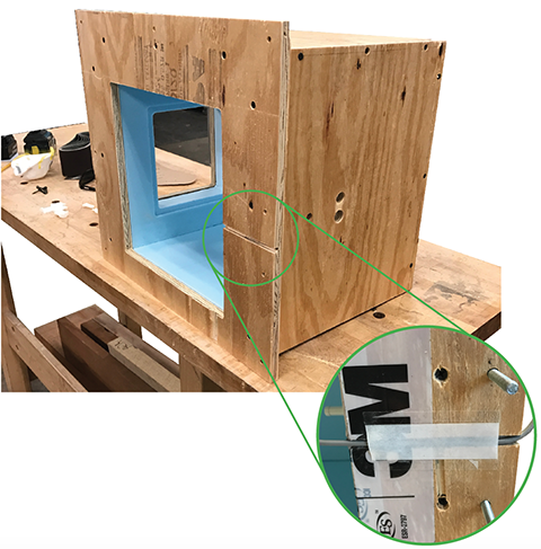
Figure 12
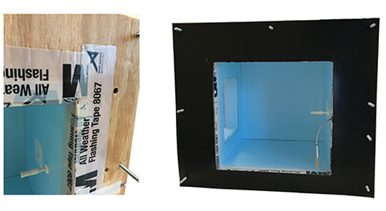
Figure 13
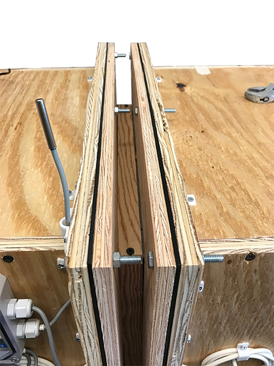
Figure 14

Figure 15
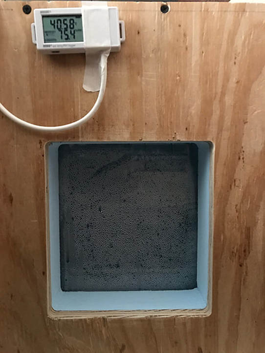
Figure 16
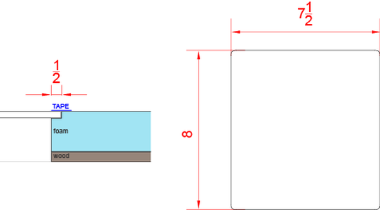
Figure 17
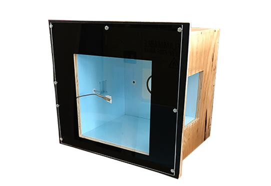
Figure 18
|
Design Use a double rabbet joint at edges to ensure no direct passage for air or water vapor. Cavities for sensors and control equipment are cut into the surface of the foam using minimal clearances to avoid thermal bridging from material reduction.
Fabrication Foam can be quickly and precisely cut using a 3-axis router, such as the C.R. Onsrud. Only one toolpath is required - use a 1/2” endmill with a feed rate of 350.0 and spindle speed of 14,000. Pieces may also be cut using available shop tools, including a table saw and drill press, sacrificing the rabbet corners for a simple butt joint. Assembly Use masking tape (or equivalent) to hold the pieces together temporarily. Masking tape is useful because it will not tear the surface of the foam when removed. Because the router bit is round, the edges of interior corners may need to be trimmed manually to ensure a tight fit. Alternatively, given the foam’s compressible nature, these edges may also be forced into place once the wood surround is applied. Design 5/8” CDX plywood is used as a protective layer around the foam. This enclosure provides a durable surface to attach specimens without penetrating the thermal barrier. Fabrication Again, the Onsrud 3-axis router is used to ensure precise, flat edge cuts. Openings align perfectly with the foam apertures. Similar to the foam, pieces may be cut with common shop tools – perimeter cuts with a table saw, interior holes with a drill press, and interior cuts with a jigsaw and a steady hand. The toolpaths used on the wood were only slightly more complex than those used for the foam. Toolpaths Drill the holes first using a 1/4” drill bit with a feed rate of 200 and spindle speed of 18,000. Then cut the wire chase and perimeter contours with a .375” flat endmill with a feed rate of 450 and spindle speed of 18,000. Be sure that the bit is cutting on the correct side of the line – at the perimeter it needs to cut outside the line but at interior openings it needs to cut inside the line. Leave .01” material behind (called an ‘onion skin’) so that the bed does not lose suction, keeping the parts from moving around between cuts. Assembly Use masking tape again to temporarily hold the pieces in place. The wood openings should align perfectly with the foam apertures. Assembly Measure 5/16” from the edge to ensure that the screw hits the centerline of the intersecting 5/8” wood. Use three screws per edge, measuring 2” from each edge and one in the center. Hardware Pre-drilled guide holes keep the plywood from cracking or splitting as screws are drilled (and countersunk) into the end grain. Use a 7/64” pilot bit for guide holes and use 1 ½” stainless steel screws to attach the wood panels. Be sure that screws do not penetrate beyond the wood barrier to ensure that no screw punctures the foam enclosure. Assembly Use a clamp to ensure that pieces do not move when drilling. (Clamp must be large enough to accommodate 16”). Face Panel Once all sides are attached, attach the face panel. Ensure that screws do not puncture thermal foam enclosure. Precisely measuring the guide holes is especially important here since the location of the receiving plywood end is not visible through the face panel. Note that this layer is included in the clear volume of the enclosure. Wire Chase When attaching the face panel, make sure that the routed surface faces away from the interior of the foam box. This small channel is used to run the surface temperature sensor cable through the thermal enclosure while providing for a flat surface to attach test specimens. Use a piece of Gorilla Tape to enclose the wire in the channel (once tape has been applied, which will be discussed later), but use a piece of masking tape to create a non-sticky path for the wire to slide along. Air Sealing Because wood is a porous material, seal the edges to prevent any lateral transfer of moisture through the face panel. 3M flashing tape is a widely accepted product for window flashing and air sealing. Pre-cut tape into 14” strips, remove backing one half at a time and apply to foam and wood, ensuring at least 1/2” overlap with foam interior. A double layer of tape may be required at corners. Neoprene Gaskets A rubber gasket is required for two reasons – first, to prevent the lateral transfer of moisture between connected face panels and second to ensure a flush, airtight fit between each chambers and the specimen, which may have a slightly textured surface. Each chamber requires its own sheet gasket. With the exception of the routed hole for the surface sensor, the neoprene dimensions can be copied directly from the face panel. The black material shown here is the neoprene gasket. This material separates each chamber from the specimen, was as noted above, may not be completely flush with the face panel. Concrete, for example, often has a textured surface that is difficult to air seal without an air gasket. Hardware Use 1/4” diameter screws, 2” length, with corresponding hex nuts. Use a hex socket to loosen and tighten the nuts. Window Panel Install a window panel to provide visual observations and occasional safety checks. Use 5/16” clear acrylic and laser cut using the following dimensions. Note: the photo here shows condensation on the window panel during an experiment. Design & Installation Seal edges with gorilla tape, ensuring a minimum of ¼” overlap with acrylic panel. The void for the panel is routed into foam to sit flush. If you choose not to countersink the acrylic, you will need to revise these dimensions to fit your opening. The corners are radiused .3/8” to match the path left behind from the end mill. Testing Panel (optional) Match the dimensions from the face panel to seal the opening. This sheet is helpful for testing box operation once controls are operational. Note: Acrylic is infrared opaque, so it is impossible to use an infrared camera to check for thermal bridges and air leaks. |