Controls (electronics)
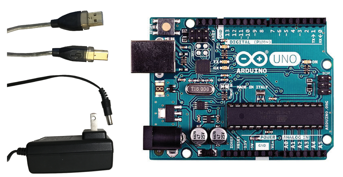
Figure 1
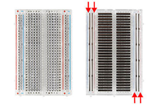
Figure 2

Figure 3
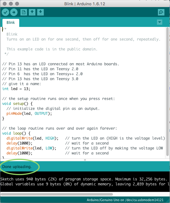
Figure 4
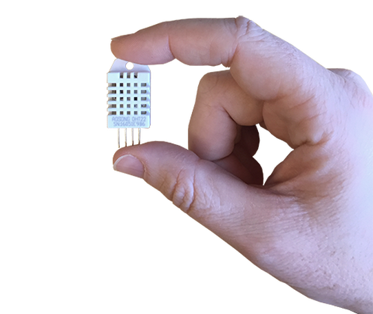
Figure 5
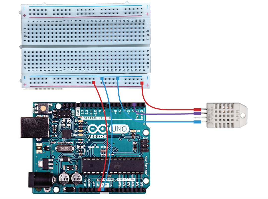
Figure 6
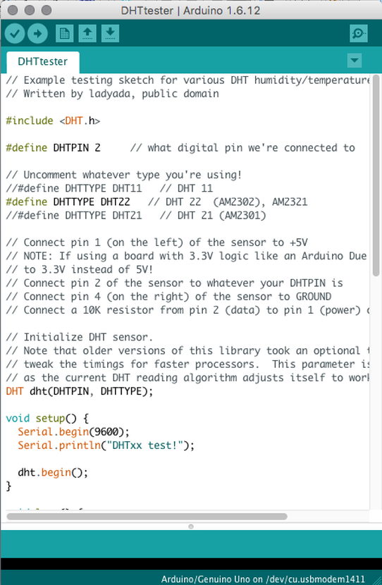
Figure 7
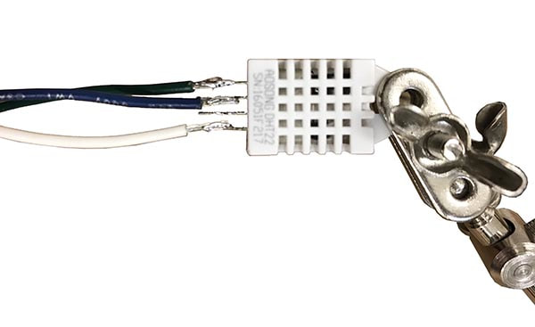
Figure 9
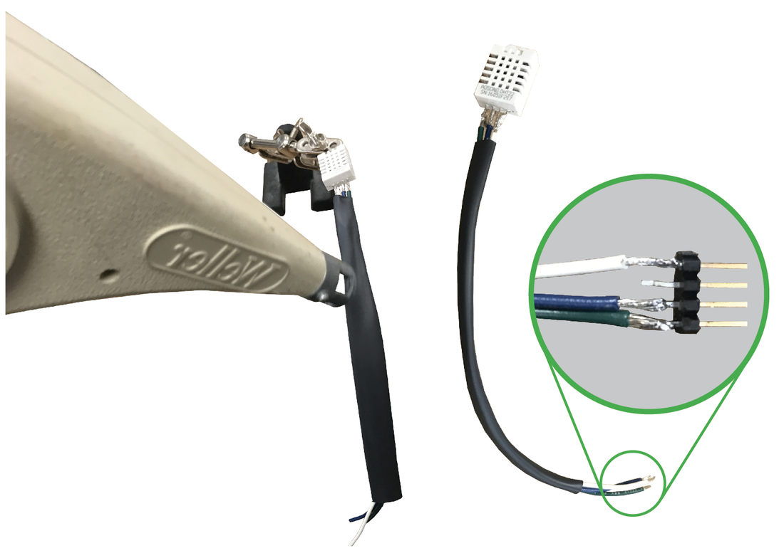
Figure 10
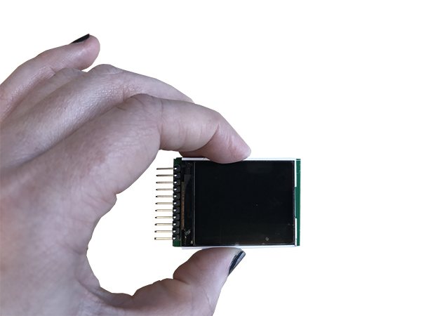
Figure 11
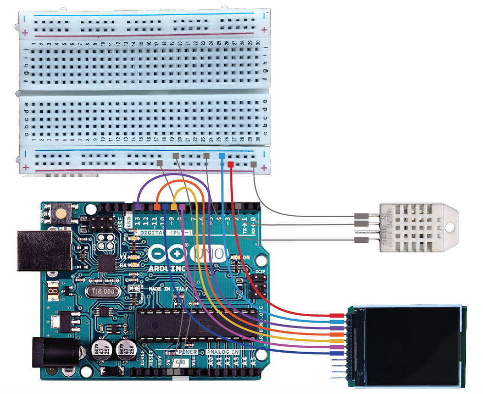
Figure 12
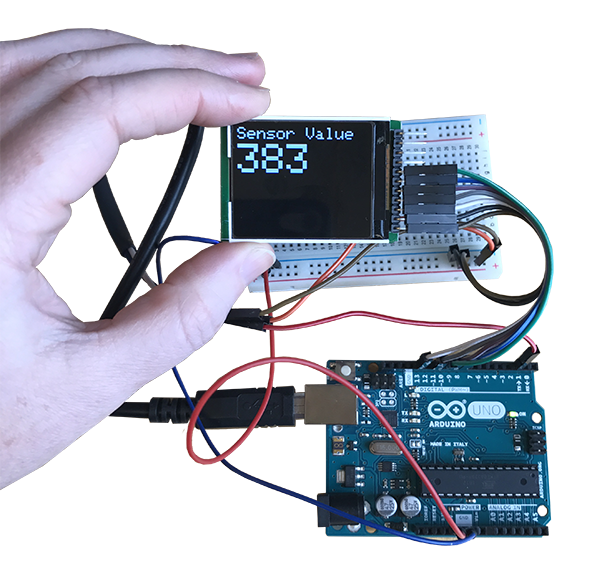
Figure 13
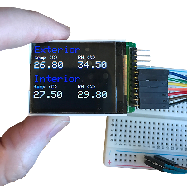
Figure 14
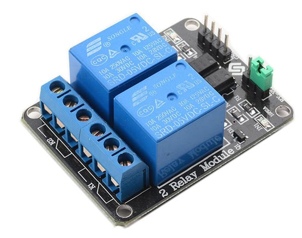
Figure 15
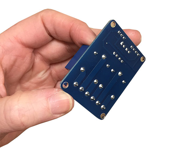
Figure 16
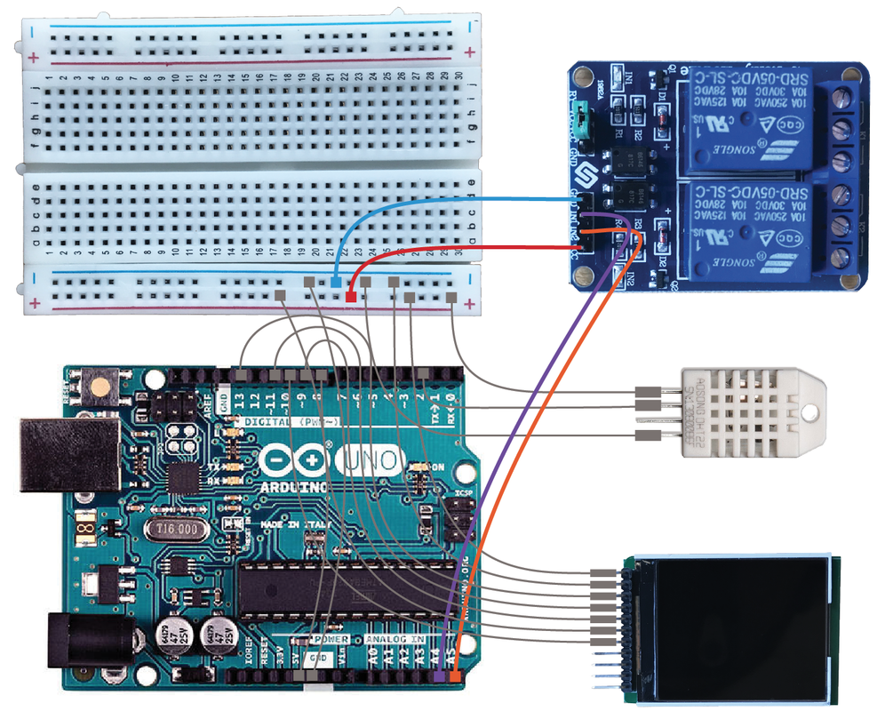
Figure 17
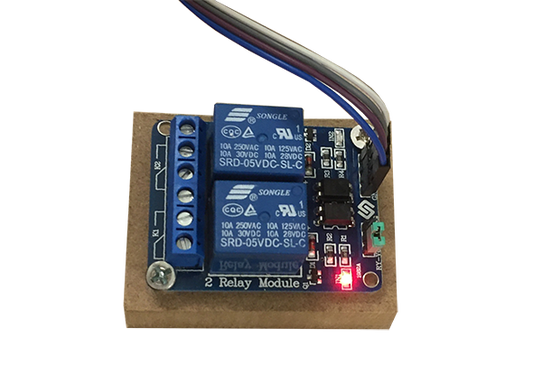
Figure 18
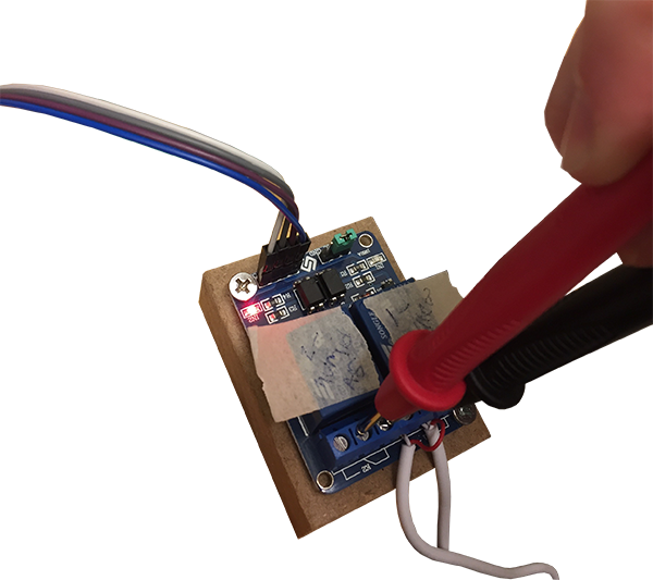
Figure 19
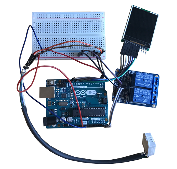
Figure 20
External Appliances
Figure 21
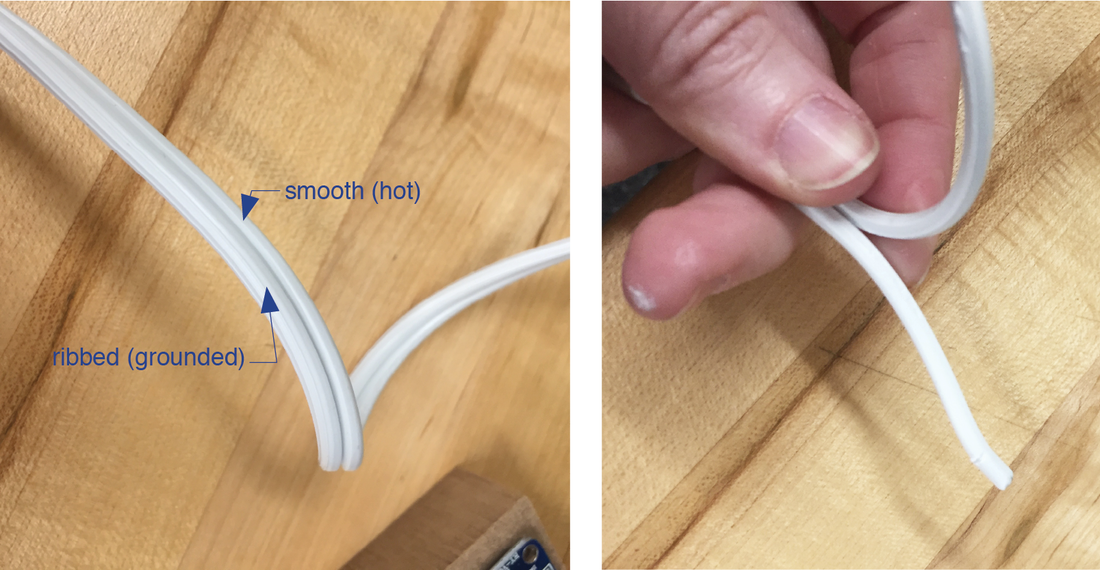
Figure 22
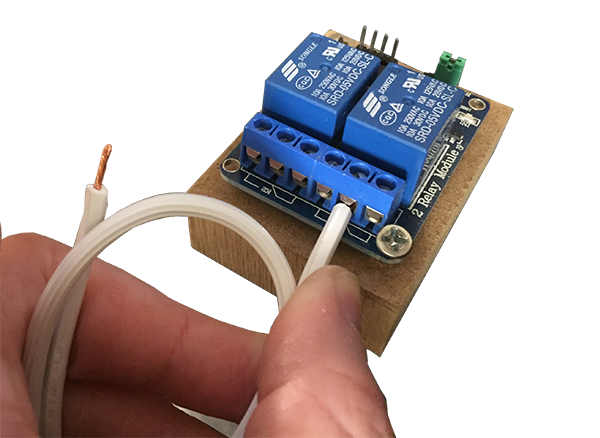
Figure 23
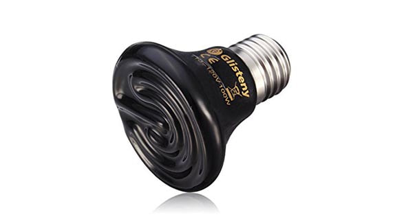
Figure 24, photo from Amazon.com
Product: Ceramic Heat, GLISTENY Mini Brooder Bulb Infrared Bulb Emitter Lamp Infrared Ceramic Bulb Heat Lamp, 25w. 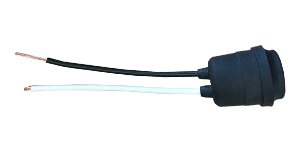
Figure 25
Product: Leviton 55 Weatherproof Lampholder, Single Circuit, 660W-250 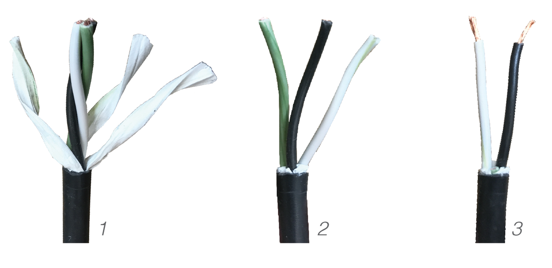
Figure 26
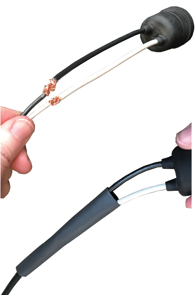
Figure 27
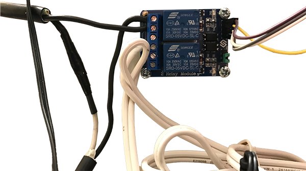
Figure 28
Commercial Sensors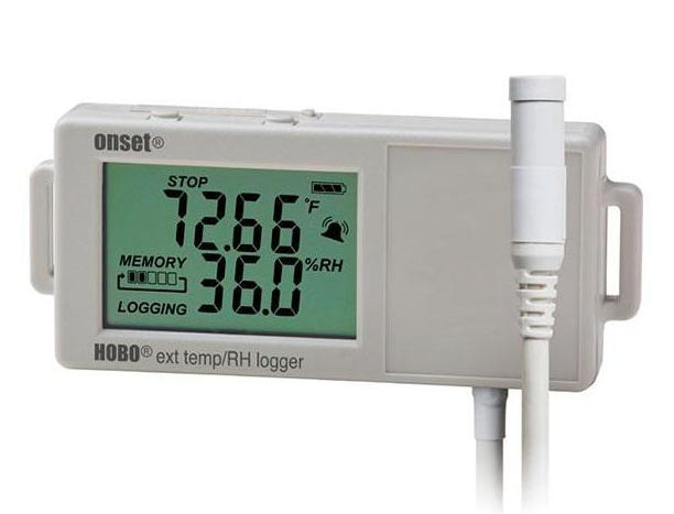
Figure 29, image by Onset
Product: Onset HOBO External Temp/RH Data Logger, Part# UX 100-023 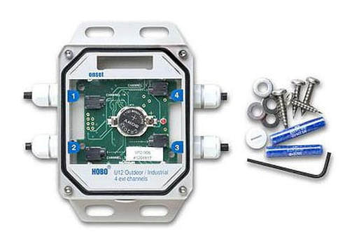
Figure 30, image by Onset
Product: Onset HOBO 4-Channel External Data Logger, Part# U12-008 |
Project Inventory
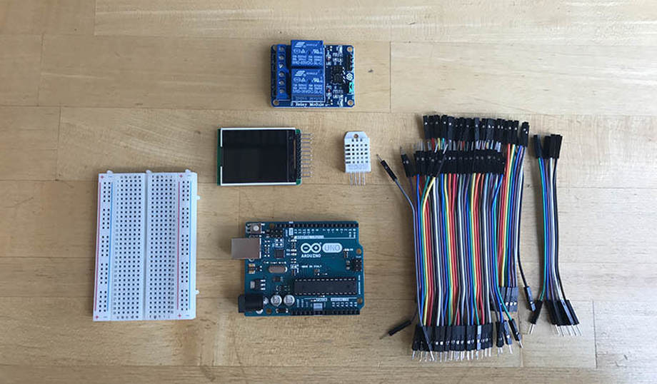
• Arduino Uno and breadboard on acrylic plate by manufacturer. • Jumper cables • Relay • (2) DHT22 temperature and humidity sensors • LCD screen Arduino Uno This project uses the open-source Arduino prototyping platform. The Uno utilizes Atmel’s low-power 8-bit microcontroller and Arduino IDE, the Integrated Development Environment for programming, which runs on all major operating systems. Arduino also has a large following of online users that share code and libraries. Cables Required: USB 2.0 Cable A/B, and AC-to-DC adapter with a 2.1mm center-positive plug. Breadboard Breadboards are a fundamental part of solderless circuit design, and are helpful when prototyping new ideas. The power rails flank the sides (running north-south) while the terminal strips (data) run east-west. The left image shows the breadboard casing while the right image shows the embedded circuitry. For this exercise, we’ll only use the left side of the board to complete the circuit. Programming the Arduino
Download and install the Arduino Desktop IDE for your operating system (or you can code online using the Arduino Web Editor). https://www.arduino.cc/en/Guide/MacOSX Using the USB cable, plug in the board to your computer. The USB will also supply power, so you’ll only need the power adapter when you want to run the arduino without your computer. When connected to power, the green LED next to “on” should light up. Once installed, open the IDE and set up your board: Tools > Board > Arduino/Genuino Tools > Port > /dev/cu.usbmodemXXXX (the 4-5 numbers at the end are custom to the device). You will not need to select a programmer for the Uno. This is a helpful link for troubleshooting: http://www.arduino.org/learning/getting-started/getting-started-arduino-uno Test Sketch: Blink Before proceeding with the setup, make sure the board is properly set up uploading one of the example sketches included with the software, such as Blink. File > Examples > 01.Basics > Blink. Once the screen says “Done uploading” the orange LED should blink every few seconds. DHT 22 The DHT22 is a low-cost digital sensor that uses a capacitive humidity sensor and a thermistor to measure ambient conditions. The product comes with a 10K resistor which needs to connect between the data pin and power (VCC). Pins: 1- VCC 2- Data 3- Null (no connection) 4- GND Circuit Diagram First, connect power (red) and ground (blue) to the breadboard to complete the circuit with male-male jumper cables. Using male-female jumper cables to connect: • Pin 1 to VCC (power) 5V. (red) • Pin 2 (data) to the Arduino port 2. Connect the 10K resister (included with the sensor) between the data and power pins. I trimmed the resistor and soldered it directly to the pins. (purple) • Pin 3 (null) – ignore this pin. • Pin 4 to GND (ground). (blue) Repeat the steps for the second sensor, connecting pin-2 to Arduino port 4. Test Code Download and install the DHT22 libraries from adafruit. Follow the instructions and make sure they are located in the correct folder. https://github.com/adafruit/DHT-sensor-library Once libraries are installed and you have restarted the IDE, open and upload the DHTtester sketch: Examples > DHT Sensor Library > DHTtester Open the serial monitor to see readings (Tools > serial monitor). There may be a 2-second delay. 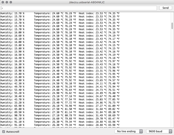
Figure 8
Extension cables Because the sensor is housed within the testing chamber, it is useful to extend the cables for the sensor. Strip ~1/4” from each end of the wire. Connect approximately 12” in length individually to each of the three pins (ignore pin-3). Solder an HDMI header to the free ends so jumper cables can be easily connected to the Arudino Treat the wires Electrical tape should only be used for short term use. Wrap the wires with shrink wrap and use a heat gun to shrink the covering. Once the cables have been extended, test it again to make sure everything still works. There should not be any changes to the code. LCD Display Screen Product: SainSmart 1.8 ST7735R TFT LCD Module with MicroSD LED Backlight. The screen is full color and easy to program using Processing-type controls. The back of the device reveals the pin labels and uses. Circuit Diagram Connections (from top to bottom, confirm with notations on back). • Pin-1 – VCC to power (red) • Pin-2 – GND to ground (blue) • Pin-3 – SCL to 13 (purple) • Pin-4 – SDA to 11 (orange) • Pin-5 – RS/DC to 9 (yellow) • Pin-6 – RES to 8 (magenta) • Pin-7 – CS to 10 (navy) • Pin-8 – MISO (none) • Pin-9 – SCLK (none) • Pin-10 – MOSI (none) • Pin-11 – CS (none) This was a helpful website: http://www.instructables.com/id/Temperature-and-Humidity-on-a-Graphical-LCD/ Test Code The screen requires the SPI.h and TFT.h libraries, which are already included with Arduino IDE versions 1.0.5 and later. Test the setup using an example sketch: File > Examples > TFT > Arduino > TFTDisplayText The screen thinks it’s reading a sensor plugged into pin A0, which we do not have, so just use this sketch to make sure the screen is properly connected. Final Display The screen provides a temperature (C) and relative humidity (RH %) reading for each sensor. Relay Controls This device is used to control power supply to appliances and equipment with line voltages. It switches the power from high (on) to low (off), essentially connecting or disrupting current from the power source. Cautionary Note This device works with line voltages, so make sure all wires are disconnected from power source before proceeding. The back of the board also poses an electrocution risk, so it is helpful to attach the relay to a piece of non-conductive scrap material (such as wood or MDF) before proceeding. The device will be re-housed in a later stage in the process. Circuit Diagram The relay has 4 pins, GND, IN1 (input1), IN2 (input 2), VCC. • Pin-1 – GND to ground (blue) • Pin-2 – IN1 to A4 (purple) • Pin-3 – IN2 to A5 (orange) • Pin-4 – VCC to power (red) Test Code – Blink Test Without plugging any of the devices into the input ports, it is possible to test basic operation and functionality. This is also helpful to better understand the controls. Use the following code: Blink Test
The IN2 LED should blink and click every few seconds. Change “RELAY2” to “RELAY1” to test the other input.
Power Supply While the code is still running, use a microcontroller to test the power supply to the device. When the IN2 LED is illuminated, for example, there should be power circulating between all three input pins on the K2 side. When the LED is off, there will not be power between the second and third input. All Connected Now that all of the devices are connected and running, it’s time to connect the external appliances. Humidifier Product: Vicks V745 warm mist humidifier. This device is a commercially available household humidifier. I actually used a 2-year old product and bought a new one for my own use. Note: when the humidifier is hooked up to the box, it needs to sit lower than the opening so the steam can rise. Wire Splitting One of the wires needs to remain intact, while the other gets cut, stripped, and stuffed into the relay. Conventional power cords have two types of wire – one is grooved or ribbed and the other is smooth. The grooved wire is grounded (neutral) while the smooth wire is ungrounded (hot). Cut the smooth (hot) wire to connect to the relay. Note: other wires (such as USB power supplies) have both wires within one casing – to reveal these wires, cut through the casing lightly with a knife in order to preserve both wires inside. Connections Insert one end of the split wire into the middle K1 input ports. Insert the other end into the port directly left of the first wire. You will repeat this step for the heater. Since there is no straight-forward sample code for this step, test the device once the heater has also been installed. Do not plug either device into a power supply yet. Heater Type The system was originally designed with a radiant mug warmer as the heat supply, which eventually was changed to a heat lamp to provide more heat. The mug warmer took two hours to change the ambient heat of the box from 22C to 26C while the heat lamp took only one hour to increase the ambient heat by 20C. Since both options use radiant heat, they not only heat slowly, but they maintain high temperatures even after the power is disconnected. If the desire is to move quickly between hot and cold ambient temperatures in the chamber, a supplemental cooling device may need to be installed. Weatherproof Lampholder Because the lamp is in a moist environment, it needs to be protected with a weatherproof socket. The lampholder comes with two 6” leads (black and white) with the free ends stripped ¾”. Black – line (hot/incoming) White – load (neutral) Power Supply Use a spare extension cord or the cord from an old appliance. You’ll need to cut about 16” from the end that includes the prongs. I used an extension cord with three prongs. Carefully remove the rubber jacket and internal paper to expose the three wires (black, white, green). Since the lampholder only has black and white wires, cut the green wire (it can live within the rubber jacket). Wire Extensions Using leftover wire from the cut extension cord, extend the length of the wire if necessary. I added 12” of length. This is a fairly simply connection – connect the black to black wire and the white to white wire. If using a 3-prong cord, you can disregard the green wire from the extension cord. Strip the ends of the wires about 3/8” and intertwine with the connecting wire. Since current has trouble flowing along sharp corners, it is helpful to fill this connection with solder to ensure a clean path for current. Heat Shrink Tubing Cover any electrical current with heat shrink tubing. Be sure to thread wires through openings in box and 3d printed holder case (which will be discussed later) before finalizing wire connections. Connections Once the devices are connected, run the sample relay code (from above) again - it may be helpful to use a longer interval so the devices have some time to heat up. The appliances will need to be plugged into a power source for this to work. Ambient Temperature/RH Due to the high humidity and temperature conditions, the manufacturer recommended the version with the probe to protect the equipment (as opposed to using an all-in-one” device). This also provides the added benefit of avoiding the free-heat from the alternative unit, which would be more noticeable in such a small volume. One device is required for each chamber. Surface Temperatures 4-circuit device is used to measure the surface temperatures at both sides of the specimen as well as an additional probe for ambient conditions in the room. Exterior unit not required, but it did provide for easy mounting and interchangeable environmental sensors. Software Both HOBO devices communicate with the computer via a USB to mini USB interface cable (which is included with purchase). They also require HOBOware software, which offers both a professional and a free version. |
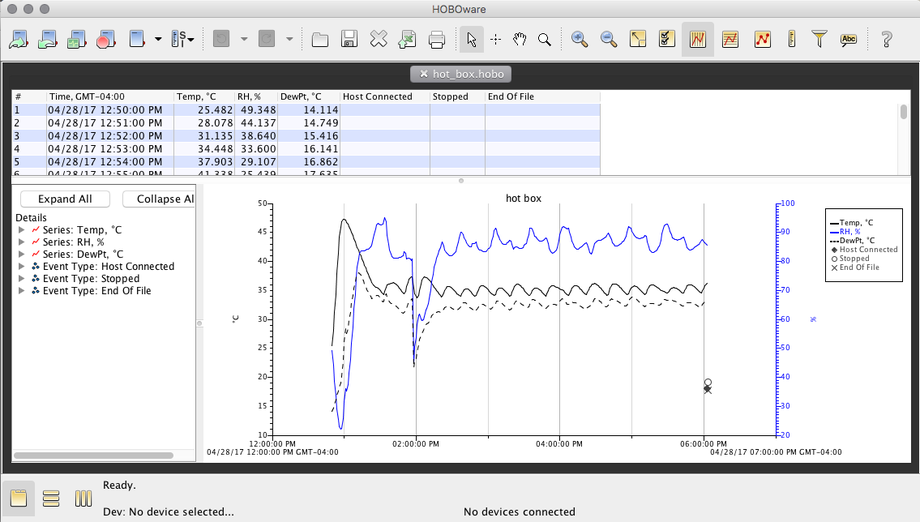
Figure 31
Calibration
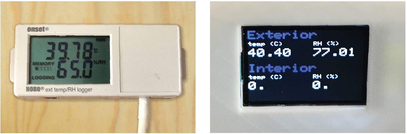
There are two different sensors in each chamber (a) DHT22 and (b) Onset Hobo. The DHT22 sensor is connected to the Arduino, so it controls the heater and humidifier. It does not record any of the readings. Meanwhile, the Hobo sensor provides the actual data readings. It is likely that the DHT22 sensor is not as precise as the Hobo sensor, so the two will need to be calibrated.
|
(a) hobo sensor
|
(b) DHT sensor
|
Figure 32
Both of the following two-hour test use a 2” piece of XPS foam to seal the hot box. The goal temperature was 36°C and the goal RH was 60%. Readings from each sensor are taken every five minutes. The graphs on the left show the readings over time while the scatterplots on the right show the readings plotted against each other, so if the sensors were both reading the same value, the points would fall on the center line.
Pre-calibrated Conditions
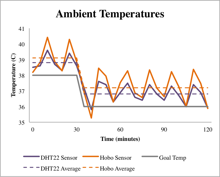
Figure 33
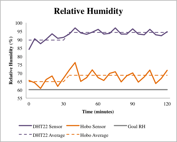
Figure 35
|
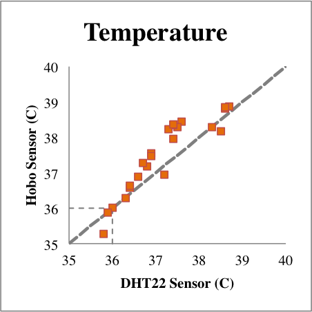
Figure 34
While the ambient temperature readings were relatively close (within 1°C), there was a significant difference (22.58%) between relative humidity values, so the code was adjusted as follows to fix this difference. 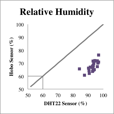
Figure 36
|
Sensor Calibration
Calibrated Conditions
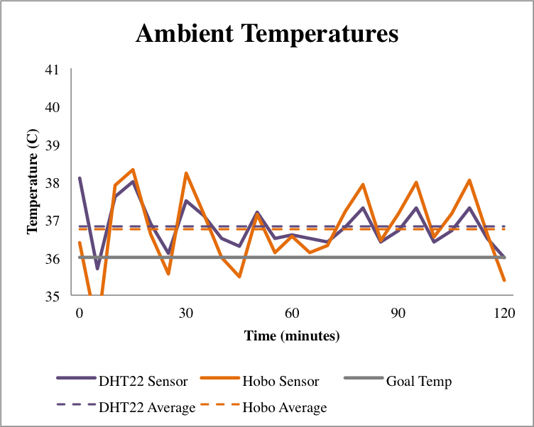
Figure 37
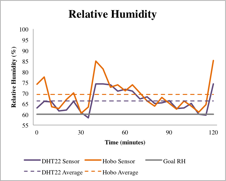
Figure 39
|
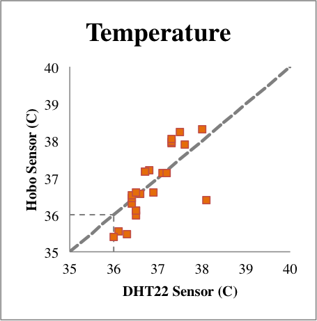
Figure 38
The post-calibration test, shown in figures 37-40, shows that the revised code worked to provide much more accurate readings. 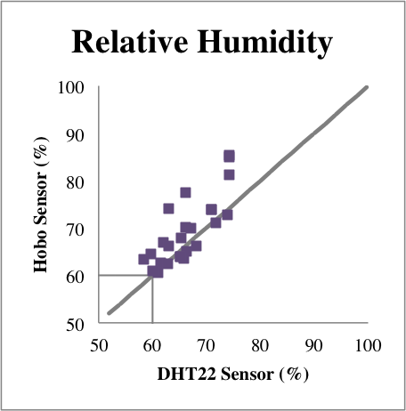
Figure 40
|
Final Code