
Natural Convection
In natural convection, the fluid motion occurs by natural means such as buoyancy. Since the fluid velocity associated with natural convection is relatively low, the heat transfer coefficient encountered in natural convection is also low.
Mechanisms of Natural Convection
Consider a hot object exposed to cold air. The temperature of the outside of the object
will drop (as a result of heat transfer with cold air), and the temperature of adjacent air to
the object will rise. Consequently, the object is surrounded with a thin layer of warmer air
and heat will be transferred from this layer to the outer layers of air.
The temperature of the air adjacent to the hot object is higher, thus its density is lower. As a result, the heated air rises. This movement is called the natural convection current. Note that in the absence of this movement, heat transfer would be by conduction only and its rate would be much lower. In a gravitational field, there is a net force that pushes a light fluid placed in a heavier fluid
upwards. This force is called the buoyancy force.
Laminar and Turbulent Natural Convection In An Enclosed Cavity
Natural convection in cubical enclosure with hot surface geometry and partial partitions has been analyzed. The geometry is a cube with wavy hot surface (three undulations) and three partitions. The investigation has been performed for different partitions lengths and Rayleigh number while the Prandtl number kept constant. This problem is solved by using the partial differential equations which are the equation of mass, momentum, and energy. The results obtained show that the hot wall geometry with partitions affects the flow and the heat transfer rate in the cavity. It has been found also that the mean Nusselt number decreases compared with the heat transfer in the undulated cubical cavity without partitions.
Natural convection in cubical enclosure with hot surface geometry and partial partitions has been analyzed. The geometry is a cube with wavy hot surface (three undulations) and three partitions. The investigation has been performed for different partitions lengths and Rayleigh number while the Prandtl number kept constant. This problem is solved by using the partial differential equations which are the equation of mass, momentum, and energy. The results obtained show that the hot wall geometry with partitions affects the flow and the heat transfer rate in the cavity. It has been found also that the mean Nusselt number decreases compared with the heat transfer in the undulated cubical cavity without partitions.
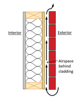
Factors Affecting Airspace R-value
1.Size and orientation of the airspace;
2. Shape of surfaces forming the airspace;
3. Reflectivity (or emissivity) of the surfaces facing the airspace;
4. For reflective airspaces, the durability and degree of fouling of the reflective surface over time;
5. Direction of heat flow relative to airspace orientation (i.e., seasonal change in heat flow direction);
6. Natural convection (movement of air within the airspace due to thermal gradients);
7. Mass air exchange with the airspace due to air leakage or venting of the airspace (caused by wind- and buoyancy-driven pressure differentials).
The Effects of Envelope Shape and Heat Source Placement on Buoyancy Ventilation: Some Preliminary Visual Experiments
Set up:
1.Plexiglass Models_to approximately dwelling envelope;
2.Metal Brick-heated or cooled as heat source or heat sink;
3.colored Inks;
4.Large tub filled with water at room temperature;
5.Electric kettle;
6.Refrigerator or freezer nearby
Test 1:
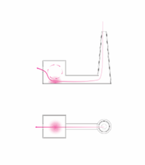
Black ink was used in first test with an envelope configuration consisting of a cube shaped chamber connected to a taller, tampering chamber with a rectangular passage, The metal brick was heated in a pot of boiling water and then placed in the cube shaped chamber. Ink was injected at the top of the tampering chamber and close to the opening on the side of the cube.
Test 1 Observation:
Ink flows down the tapering structure, and travels toward the heated
brick, eventually stabilizing in a stratified manner in the cube shaped
chamber as the warmer fluids rises.Some of ink continues to escape
from the opening at the left.
Set up:
1.Plexiglass Models_to approximately dwelling envelope;
2.Metal Brick-heated or cooled as heat source or heat sink;
3.colored Inks;
4.Large tub filled with water at room temperature;
5.Electric kettle;
6.Refrigerator or freezer nearby
Test 1:
Black ink was used in first test with an envelope configuration consisting of a cube shaped chamber connected to a taller, tampering chamber with a rectangular passage, The metal brick was heated in a pot of boiling water and then placed in the cube shaped chamber. Ink was injected at the top of the tampering chamber and close to the opening on the side of the cube.
Test 1 Observation:
Ink flows down the tapering structure, and travels toward the heated
brick, eventually stabilizing in a stratified manner in the cube shaped
chamber as the warmer fluids rises.Some of ink continues to escape
from the opening at the left.
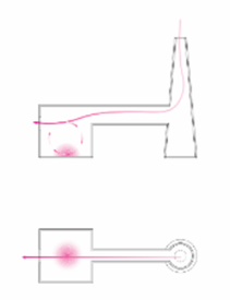
Test 2
Pink ink was used in test 2. In this version of the model,the rectangular passage was elevated and connected to the middle of the tapering chamber to the top of the cube shaped chamber.he metal brick was heated in a pot of boiling water and then placed in the cube shaped chamber, Ink was injected at the top of the tampering chamber.
Test 2 Observation
At first the ink floods the tapering chamber when it is added at the top, eventually, the placement of the heated brick in the cube-shaped chamber pulls fluid from the tapering chamber in a distinct form through the rectangular corridor. We noticed how the ink literally pours over the heated brick and ultimately engulf it. This creates a stratification within the corridor, the ink stays close to the base, in the cube shaped chamber it stays close to the heated brick, and in the tapering chamber it becomes concentrated at the bottom as well.
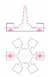
Test 3
Blue ink was used in a tri-chamber set-up. A central tapering chamber is flanked by two identical cube-shaped chambers and connected to them with identical rectangular corridors. A heated block is placed in one of the cubed chambers. Blue ink was injected at the top of the tapering chamber.
Test 3 Observation
Initially, the ink dissipates into the two cube-shaped chambers in a seemingly similar way. Eventually, however, ink flows at a faster rate into the chamber that contains the heated brick, eventually engulfing the brick and also leaving the empty chamber to move instead into the chamer with the brick. Some of the ink also settles at the base of the central chamber.
Sources:
1. International Journal of Heat and Mass Transfer Volume 27, Issue 5, May 1984, Pages 755-772;
2. https://www.sfu.ca/~mbahrami/ENSC%20388/Notes/Natural%20Convection.pdf;
3. Air Space R-Value, Independent Science & Engineering Support, http://www.appliedbuildingtech.com/system/files/modules/node/110/educationpptairspacervalue.pdf;
4. The effects of envelope shape and heat source placement on buoyancy ventilation: some preliminary visual experiments, Farhad Mirza;